Pipe belt monitoring device and method

A technology of monitoring device and pipe belt, which is applied in the direction of measuring device, electromagnetic measuring device, and electric device, etc., can solve the problems of long pipe belt distance, deteriorating production environment, and long-distance material leakage, so as to achieve timely monitoring and alarm, and reduce Labor intensity, the effect of improving the service life

Inactive Publication Date: 2020-05-15
SHANDONG IRON & STEEL CO LTD
View PDF11 Cites 0 Cited by
  • Summary
  • Abstract
  • Description
  • Claims
  • Application Information

AI Technical Summary

Problems solved by technology

[0003] However, with the prolongation of the running time of the pipe belt machine, the pipe belt and its related equipment will be slightly deformed, which is prone to longitudinal twisting of the pipe belt (that is, when forming a round pipe, the overlapping position of the two edges of the pipe belt is at the circumference of the round pipe. upward shift) phenomenon
When the pipe belt is twisted, if it cannot be found and adjusted in time, there will be long-distance material leakage or even a vicious event of pipe belt twisting in severe cases, which will affect normal production, increase production costs, deteriorate the production environment, and increase the labor intensity of workers.
[0004] At present, the monitoring method of the pipe belt by the unit using the pipe belt is the method of manual inspection. This method is limited by factors such as the long distance of the pipe belt, the difference in day and night light, and manpower. It is often the case that the pipe belt torsion is not detected in time. As a result, material leakage or even pipe breakage occurs from time to time

Method used


Image

  • Pipe belt monitoring device and method
  • Pipe belt monitoring device and method

Examples


Embodiment Construction

[0028] The invention provides a pipe belt monitoring device, which can better ensure the normal operation of the pipe belt.

[0029] The following will clearly and completely describe the technical solutions in the embodiments of the present invention with reference to the accompanying drawings in the embodiments of the present invention. Obviously, the described embodiments are only some, not all, embodiments of the present invention. Based on the embodiments of the present invention, all other embodiments obtained by persons of ordinary skill in the art without making creative efforts belong to the protection scope of the present invention.

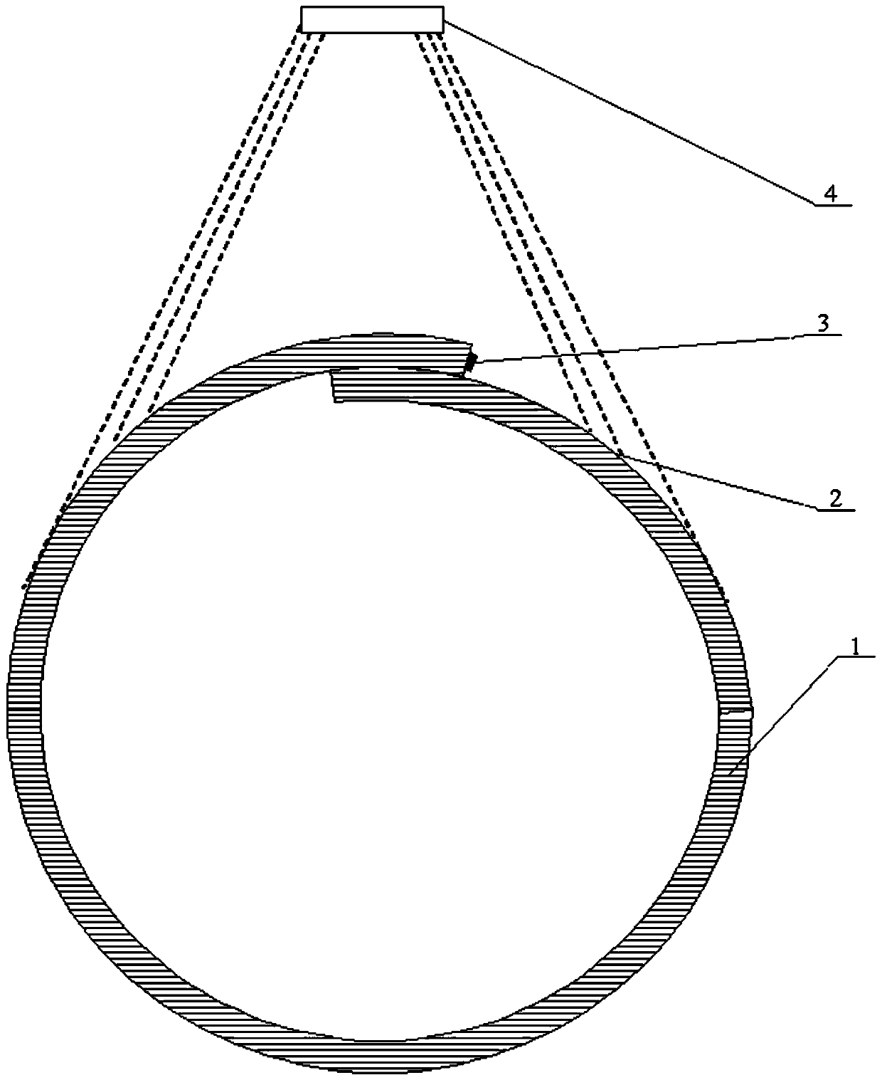
[0030] Such as figure 1 As shown, the embodiment of the present invention provides a pipe belt monitoring device for monitoring whether the pipe belt 1 is twisted and giving an alarm when it is twisted. The pipe belt monitoring device includes a magnetic component 3, a magnetic induction sensor 4 and an alarm. Among them, the magnetic ...


PUM


Abstract

The invention discloses a pipe belt monitoring device and method. The pipe belt monitoring device comprises a magnetic part arranged on a pipe belt; a plurality of magnetic induction sensors arrangedalong the conveying path of the pipe belt and can sense the magnetic components; and an alarm in communication connection with the magnetic induction sensor and can send out alarm information according to induction signals sent by the magnetic induction sensor. According to the pipe belt monitoring device, monitoring and alarming of torsion of the pipe belt can be automatically realized, and monitoring and alarming are timely and accurate, manual inspection is not needed any more, the phenomena of material leakage, shutdown, pipe belt tearing and the like caused by the fact that pipe belt torsion cannot be found and aligned in time due to the fact that manual inspection is not in place are eliminated, the labor intensity of workers is greatly reduced, the service life of the pipe belt is prolonged, and normal work of the pipe belt is better guaranteed.

Description

technical field [0001] The invention relates to the technical field of pipe belt machines, in particular to a pipe belt monitoring device, and also relates to a pipe belt monitoring method applicable to the above pipe belt monitoring device. Background technique [0002] Tube belt conveyor is a kind of continuous conveying equipment developed on the basis of ordinary belt conveyor. The conveyed material is completely enclosed in a round tube and runs stably with the belt. It is environmentally friendly, flexible in process layout, can lift materials at a large angle, and occupies an area along the line. Small area, easy maintenance, long service life and other advantages. Now it is widely used in metallurgy, construction, food processing industry, etc. [0003] However, with the prolongation of the running time of the pipe belt machine, the pipe belt and its related equipment will be slightly deformed, which is prone to longitudinal twisting of the pipe belt (that is, when ...

Claims


Application Information

Patent Timeline
IPC IPC(8): G01B7/00
CPCG01B7/003
Inventor 李建云魏保忠杜彧魏泽华刘智伟亓海录王宏伟江丹董晓春耿斐
Owner SHANDONG IRON & STEEL CO LTD
Why Eureka
Try Eureka