Soil sampling device for phyllostachys praecox shoot planting

A technology for soil sampling and bamboo shoots, applied in the field of soil sampling devices for planting thunder bamboo shoots, can solve the problems of lower sampling efficiency, laborious operation, troublesome operation, etc., and achieve the effect of improving sampling efficiency and high sampling efficiency

Active Publication Date: 2020-05-15
江西竹海农业发展有限公司
View PDF8 Cites 5 Cited by
  • Summary
  • Abstract
  • Description
  • Claims
  • Application Information

AI Technical Summary

Problems solved by technology

[0002] In the process of planting thunder bamboo shoots, it is necessary to sample the soil, further analyze the components of the soil sample, and fertilize according to the needs. In order to improve the representativeness of the sampling, it is necessary to take multiple samples according to the grid spacing. The traditional sampling device uses a sampling rod , the sampling rod is manually inserted into the soil, the operation is laborious, and the soil is discharged from the sampling rod at the same time, the operation is troublesome and the sampling efficiency is reduced

Method used


Image

  • Soil sampling device for phyllostachys praecox shoot planting
  • Soil sampling device for phyllostachys praecox shoot planting
  • Soil sampling device for phyllostachys praecox shoot planting

Examples


Embodiment 1

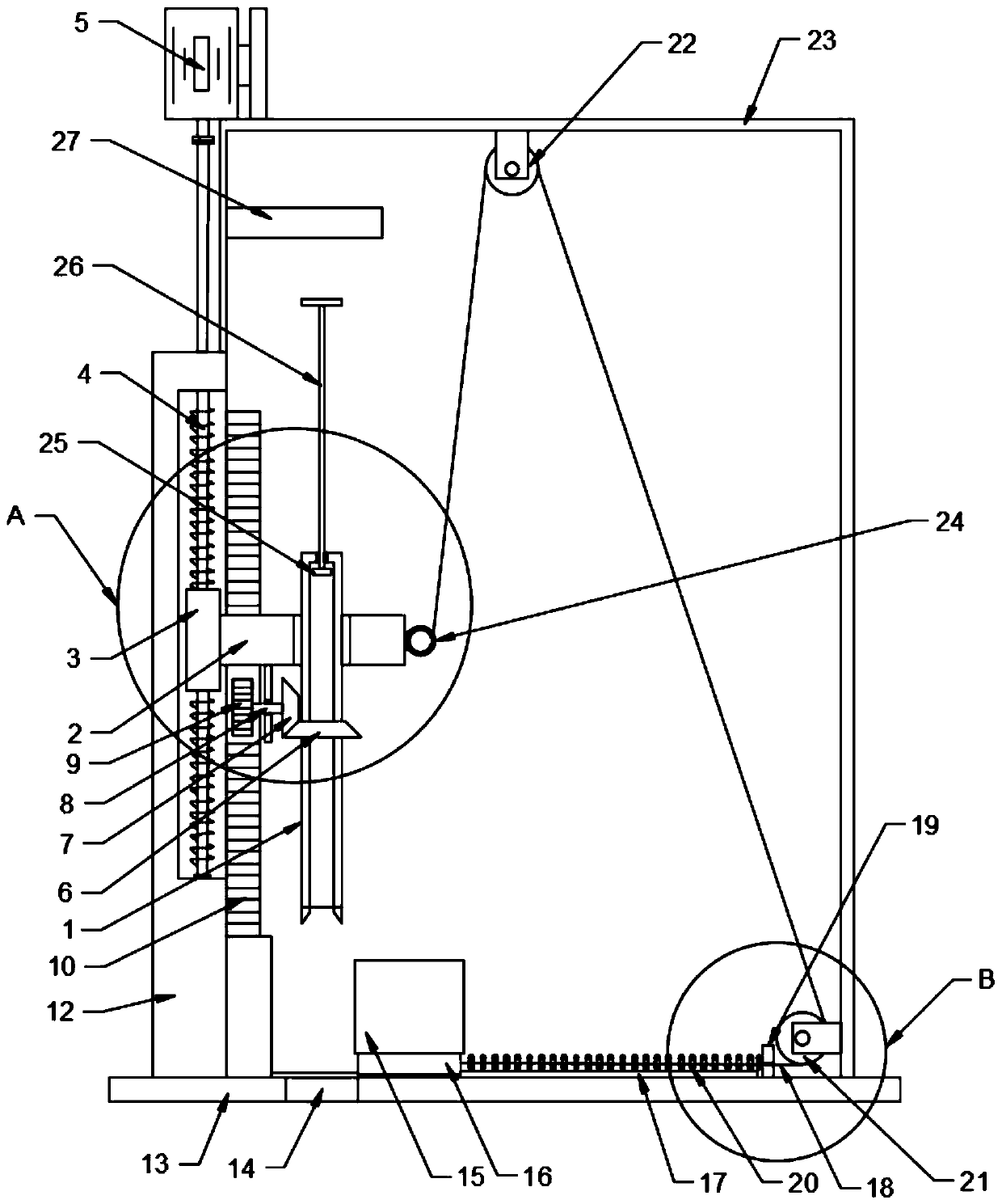
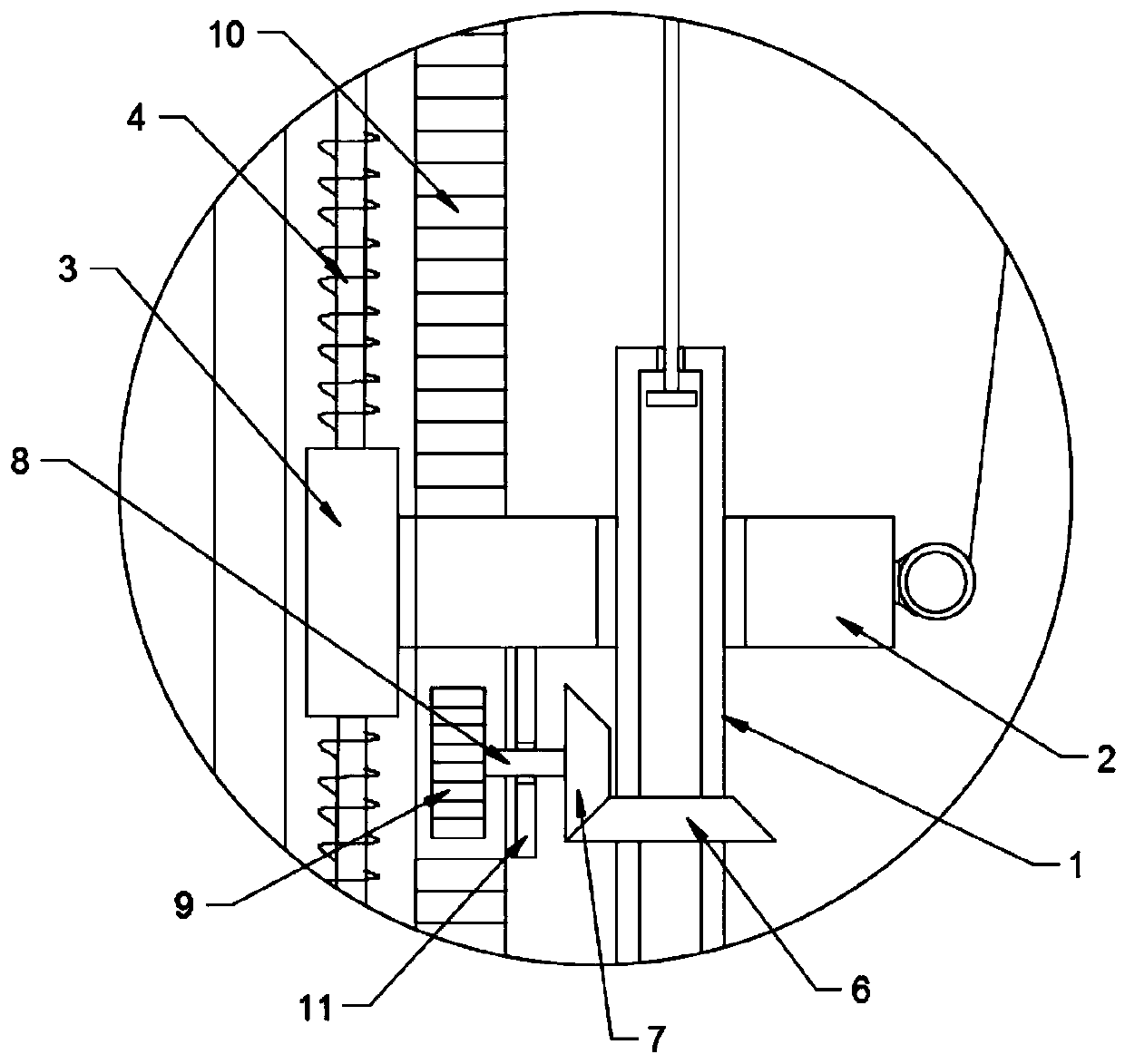
[0021] see Figure 1-4 , in an embodiment of the present invention, a soil sampling device for planting thunder bamboo shoots includes a sampling mechanism and a blanking mechanism; The plate 2 is rotatably connected with the lifting plate 2 through a bearing sleeve; one side of the lifting plate 2 is fixedly connected with a moving block 3, and the moving block 3 is nested with a chute plate 12, and the chute plate 12 is equipped with a vertical chute, the moving block 3 is nested in the vertical chute and is slidably connected with the vertical chute; Extending to the top of the chute frame 12 and connected to the output shaft of the stepping motor 5 through a coupling, specifically, the stepping motor 5 drives the screw mandrel 4 to rotate, and the screw mandrel 4 drives the moving block 3 to move up and down in the vertical chute , the moving block 3 drives the lifting plate 2 and the sampling cylinder 1 on it to move up and down to carry out vertical sampling, the height...

Embodiment 2

[0026] The difference between this embodiment and Embodiment 1 is that in order to reduce manual operations, a steel wire 18 is fixedly connected to the end of the sliding seat 16, the steel wire 18 runs through the limiting plate 19, and a spring 20 is arranged between the limiting plate 19 and the sliding seat 16. , the spring 20 is sleeved on the steel wire 18, and the limiting plate 19 is fixedly connected with the bottom plate 13; The elastic coil 24 is fixedly connected to the end of the lifting plate 2; the first fixed pulley 21 is fixedly connected to the side wall of the protective cover 23, and the second fixed pulley 22 is fixedly connected to the top plate of the protective cover 23; A volute spring is provided inside the elastic reel 24, which is similar to the internal structure of a tape measure. The stiffness coefficient of the vortex spring is smaller than that of the spring 20. Specifically, when the sampling cylinder 1 moves to the top of the blanking cylinde...


PUM


Abstract

The invention discloses a soil sampling device for phyllostachys praecox shoot planting. The soil sampling device comprises a sampling mechanism and a blanking mechanism, wherein the sampling mechanism comprises a sampling barrel rotating up and down, a pushing plate is embedded in the sampling barrel, a pushing rod is fixedly connected to the upper end of the pushing plate, and an abutting plateis arranged above the pushing rod. By arranging a moving block, a lifting plate and a transmission mechanism comprising a sleeving gear, a transmission shaft, a driving gear and a transmission gear, vertical rotation of the sampling barrel is achieved, and high sampling efficiency is achieved; and by arranging a blanking barrel, a sliding seat, a sliding rail, a steel wire, an elastic winding barrel, a pushing plate, a pushing rod and an abutting plate, automatic collection of a soil sample is achieved, and the sampling efficiency is improved.

Description

technical field [0001] The invention relates to the field of equipment for planting bamboo shoots, in particular to a soil sampling device for planting bamboo shoots. Background technique [0002] In the process of planting thunder bamboo shoots, it is necessary to sample the soil, further analyze the components of the soil sample, and fertilize according to the needs. In order to improve the representativeness of the sampling, it is necessary to take multiple samples according to the grid spacing. The traditional sampling device uses a sampling rod , The sampling rod is manually inserted into the soil, and the operation is laborious. At the same time, the soil is discharged from the sampling rod, which is troublesome to operate and reduces the sampling efficiency. Contents of the invention [0003] The object of the present invention is to provide a kind of soil sampling device for planting Lei Bamboo shoots, to solve the problems raised in the above-mentioned background ...

Claims


Application Information

Patent Timeline
Patent Type & Authority Applications(China)
IPC IPC(8): G01N1/08
CPCG01N1/08Y02W90/10
Inventor 胡宏龙陈城城雷明华
Owner 江西竹海农业发展有限公司
Why Eureka
Try Eureka