Supercharge Your Innovation With Domain-Expert AI Agents!

A current output power distribution switching circuit

A technology for switching circuits and currents, which is applied in the direction of DC network circuit devices, circuit devices, emergency protection circuit devices, etc., and can solve the problems of not being able to satisfy the current active and passive output at the same time, the signal cannot be transmitted normally, and the equipment is broken. To achieve the effect of simple structure, perfect function, and avoiding misjudgment

Active Publication Date: 2021-09-03
ZHEJIANG SUPCON TECH +1
View PDF4 Cites 0 Cited by
  • Summary
  • Abstract
  • Description
  • Claims
  • Application Information

AI Technical Summary

Problems solved by technology

[0004] The present invention mainly solves the problem that the original technology cannot satisfy current active and passive output functions at the same time, or needs to increase ports, and needs to exchange positive and negative signal lines when internal and external power distribution; provides a current output power distribution switching circuit that can simultaneously meet Active and passive output functions of current signals, without adding ports, without exchanging positive and negative signal lines during internal and external power distribution, with anti-reverse connection protection function, high reliability
The present invention also solves the problem in the prior art that both inside and outside are active at the same time, and the equipment will be reversed and broken, and at the same time, passive will cause the signal to fail to transmit normally; it provides a current output power distribution switching circuit, which can detect whether the inside and outside are active or not at the same time. source, automatically switching to the correct circuit

Method used


Image

  • A current output power distribution switching circuit
  • A current output power distribution switching circuit
  • A current output power distribution switching circuit

Examples


Embodiment

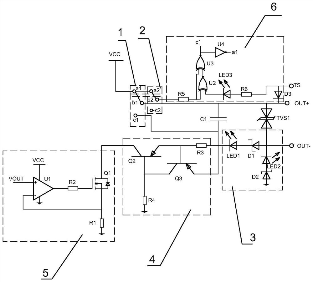
[0029] A current output power distribution switching circuit of this embodiment, such as figure 1 As shown, it includes the positive terminal OUT+ and the negative terminal OUT- connected to the external load device. There is a filter capacitor C1 and a bidirectional diode TVS1 between the positive terminal OUT+ and the negative terminal OUT-. The bidirectional diode TVS1 can suppress the Instantaneous high-voltage interference to prevent its incoming subsequent current from affecting the normal operation of the module.

[0030] The circuit also includes an internal power supply VCC, a function selection switch 1, a current limiting module 4, a feedback module 5, and a guiding module 3 connected to the input end of the current limiting module 4 connected in sequence. The function selection switch 1 is linked with a detection switch 2, and the detection switch 2 is connected with a logic judgment module 6.

[0031] The feedback module 5 includes an operational amplifier U1, a ...


PUM


Abstract

The invention discloses a current output power distribution switching circuit. To overcome the fact that the original technology cannot satisfy both the current active and passive output functions at the same time. At the same time, the active will pour into the device and damage the equipment. At the same time, the passive will cause the signal to not be transmitted normally, or the positive and negative signal lines need to be replaced when adding ports and internal and external power distribution. problem, the present invention adopts an internal power supply, a function selection switch, a current limiting module and a feedback module connected in sequence, the input end of the current limiting module is connected with a guiding module, and the function selection switch is a controlled electromagnetic switch linked with a detection switch; The switch is also connected with a logic judgment module for judging the power supply situation. It uses a function selection switch to choose one of the two, and at the same time meets the output requirements. The safety of the circuit; judging whether the circuit is active or passive at the same time, avoiding manual errors and improving reliability.

Description

technical field [0001] The invention relates to the field of power distribution, in particular to a current output power distribution switching circuit. Background technique [0002] For instruments with AO current output function (usually 4~20mA standard signal), such as isolator, recorder, PLC, etc., due to the variety of equipment or measurement equipment (such as DCS system, PLC, actuator, etc.) on the current input side , complicated, and there is no unified standard, often encounter the problem of who will provide the power supply of AO current output. From the perspective of field application, most of the cases are provided by the current output module itself, that is to say, it is used as a current signal source to output a standard 4~20mA current signal; but sometimes the current input side already has a power supply, which needs to be provided by the current output device A 4~20mA passive signal is usually called LOOP measurement. If the input and output devices ...

Claims


Application Information

Patent Timeline
Patent Type & Authority Patents(China)
IPC IPC(8): H02J1/00H02H11/00
CPCH02H11/002H02J1/00
Inventor 童灵薛斌郭佛保俞利明
Owner ZHEJIANG SUPCON TECH
Features
  • R&D
  • Intellectual Property
  • Life Sciences
  • Materials
  • Tech Scout
  • Unparalleled Data Quality
  • Higher Quality Content
  • 60% Fewer Hallucinations
Learn More