Hydraulic reversing mechanism

A reversing mechanism and hydraulic technology, which is used in cleaning methods using liquids, wellbore/well components, earth-moving drilling, etc., can solve the problems of fixed flushing direction, insufficient flushing operation, and weakened flushing ability, etc. To achieve convenient and quick disassembly and maintenance, to meet the cleaning operation, the effect of sufficient flushing operation

Pending Publication Date: 2020-05-19
JEREH ENERGY SERVICES
View PDF0 Cites 111 Cited by
  • Summary
  • Abstract
  • Description
  • Claims
  • Application Information

AI Technical Summary

Problems solved by technology

The current conventional sand washing tool is a common flushing head with holes or nozzles or a rotary flushing tool, which has the following disadvantages: when using a common flushing head with holes or nozzles for flushing operations, the flushing direction of the flushing head is not fixed. Changed, easily lead to insufficient flushing
When a rotary flushing tool is used, the rotation of the rotary nozzle is driven by the reaction force of the high-pressure liquid. When the displacement is increased for well flushing operations, the rotary nozzle will rotate at a very fast speed, resulting in a serious atomization effect , the flushing ability is weakened

Method used


Image

  • Hydraulic reversing mechanism
  • Hydraulic reversing mechanism
  • Hydraulic reversing mechanism

Examples


Embodiment Construction

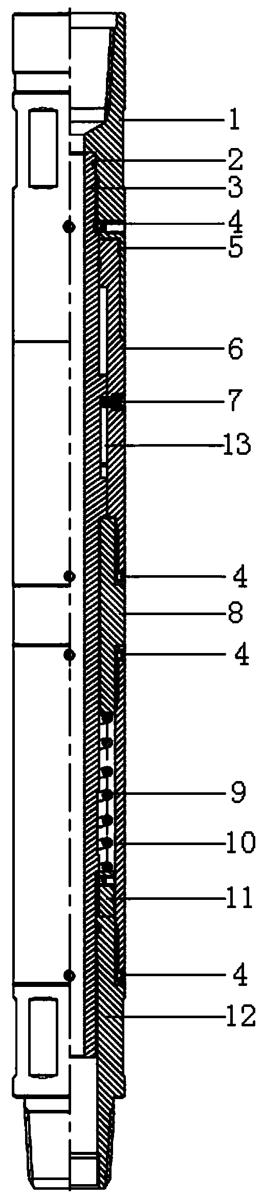
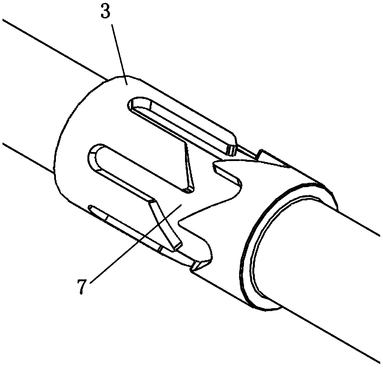
[0019] Such as Figures 1 to 2 As shown, a hydraulic reversing mechanism includes an upper joint 1, a central shaft 3, a guide ring 5, an upper housing 6, a guide pin 7, a connecting nipple 8, a compression spring 9, a lower housing 10, and a limit sleeve 11 and the lower joint 12, the upper joint 1 and the central shaft 3 are fixed and sealed connected, the guide ring 5 is arranged between the contact surface of the upper joint 1 and the upper shell 6, and the guide ring 5 is used for the rotation of the upper shell 6 in the guide. The upper casing 6 is connected to the short joint 8, the lower casing 10 and the lower joint 12 are slidably arranged on the outside of the central axis 3, and the upper casing 6 is provided with a guide pin 7 corresponding to the position of the guide pin 7. A guide groove 13 is set on the central axis 3 of the upper housing 6, and the guide pin 7 can rotate in the guide groove 13. One end of the upper housing 6 is connected to the upper joint 1...


PUM


Abstract

The invention discloses a hydraulic reversing mechanism. The hydraulic reversing mechanism comprises an upper joint, a center shaft, a guide ring, an upper shell, a guide pin, a connection nipple, a compression spring, a lower shell, a limiting sleeve and a lower joint, wherein the upper joint is connected with the center shaft, the guide ring is arranged between the upper joint and the upper shell, and the upper shell, the connection nipple, the lower shell and the lower joint can be slidably arranged on the outer side of the center shaft. The guide pin is arranged on the upper shell, a guidegroove is formed in the portion, corresponding to the guide pin, of the center shaft, the guide pin can rotate in the guide groove, a compression cavity is defined by the connection nipple, the lowershell, the lower joint and the center shaft, and the compression spring and the limiting sleeve are arranged in the compression cavity. The hydraulic reversing mechanism has the benefits that the hydraulic reversing mechanism can be used for rotational reversing of a sand washing tool, the washing operation is more sufficient, no atomization is generated, and the washing capacity is ensured. According to the hydraulic reversing mechanism, reversing is achieved under the hydraulic action, the structure is simple, and convenience is brought to installation, disassembly and maintenance. The large-discharge-capacity cleaning work can be met, and rotary jetting to the washing tool can be achieved.

Description

technical field [0001] The invention relates to the technical field of oil exploitation equipment, in particular to a hydraulic reversing mechanism. Background technique [0002] In oil extraction operations, due to the production of sand and other impurities in the formation, the productivity of the production well will be greatly reduced. In order to increase the productivity again, it is necessary to wash the sand and impurities at the bottom of the well. Conventional sand washing tools are common flushing heads with holes or nozzles or rotary flushing tools at present, which have the following disadvantages: when using common flushing heads with holes or nozzles for flushing operations, the flushing direction of the flushing head is not fixed. Changed, it is easy to cause insufficient flushing. When using a rotary flushing tool, the rotation of the rotary nozzle is driven by the reaction force of the high-pressure liquid. When the displacement is increased for well flus...

Claims


Application Information

Patent Timeline
Patent Type & Authority Applications(China)
IPC IPC(8): B08B3/02B08B13/00E21B21/00
CPCB08B3/02B08B13/00E21B21/00
Inventor 李文清于智慧韩滔
Owner JEREH ENERGY SERVICES
Why Eureka
Try Eureka