Shaft transmission structure of variable-speed bicycle

A bicycle and shaft transmission technology, applied in the direction of vehicle gearbox, rotary transmission device, wheel transmission device, etc., can solve the problems of overweight vehicle body, reduce transmission efficiency, difficult assembly and maintenance, and reduce the requirements for matching accuracy. , the effect of reducing the difficulty of production and assembly, and reducing the cost of use

Active Publication Date: 2020-05-19
兰溪市驰航机械股份有限公司
View PDF12 Cites 2 Cited by
  • Summary
  • Abstract
  • Description
  • Claims
  • Application Information

AI Technical Summary

Problems solved by technology

[0003] Although the gear transmission has a relatively high transmission ratio, it also requires high precision, while the long axis of the shaft-driven bicycle is connected to the center shaft and the rear shaft at the same time, which requires higher matching precision, which increases the difficulty of production and assembly. Difficulty, especially, due to high assembly requirements, it is difficult for non-professionals to assemble and maintain it, which restricts the popularization of shaft transmission
[0004] Secondly, the existing shaft-driven bicycles usually realize the speed change through the gearbox installed at the rear axle position. On the one hand, it will increase the difficulty of vehicle production and assembly, and at the same time cause the vehicle body to be too heavy, and the center of gravity is also biased towards the rear. On the other hand, the gearbox It also increases the difficulty of vehicle maintenance, reduces the reliability of shaft-driven bicycles, and reduces the transmission efficiency. Therefore, shaft-driven bicycles usually do not have a speed change function.

Method used


Image

  • Shaft transmission structure of variable-speed bicycle
  • Shaft transmission structure of variable-speed bicycle
  • Shaft transmission structure of variable-speed bicycle

Examples


Embodiment Construction

[0022] The following will clearly and completely describe the technical solutions in the embodiments of the present invention with reference to the accompanying drawings in the embodiments of the present invention. Obviously, the described embodiments are only some, not all, embodiments of the present invention. Based on the embodiments of the present invention, all other embodiments obtained by persons of ordinary skill in the art without making creative efforts belong to the protection scope of the present invention.

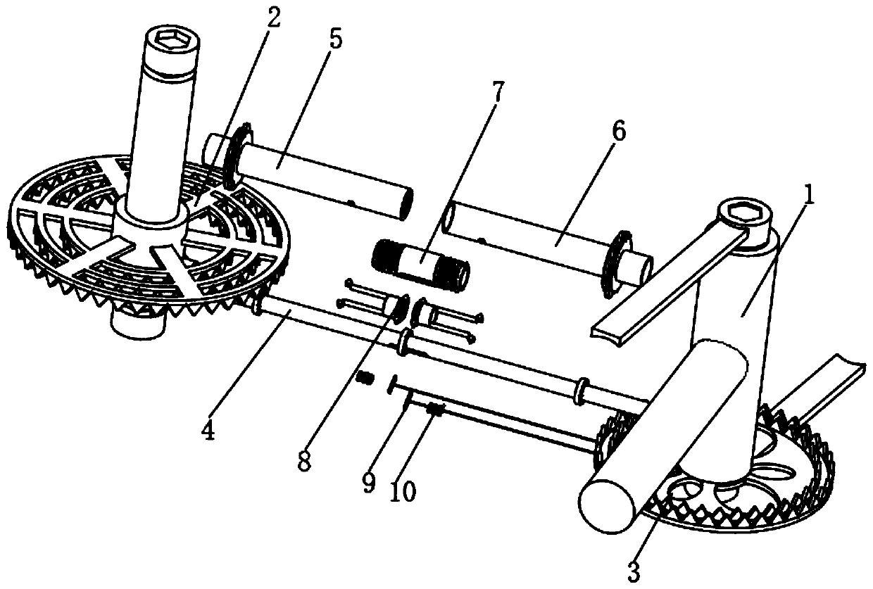
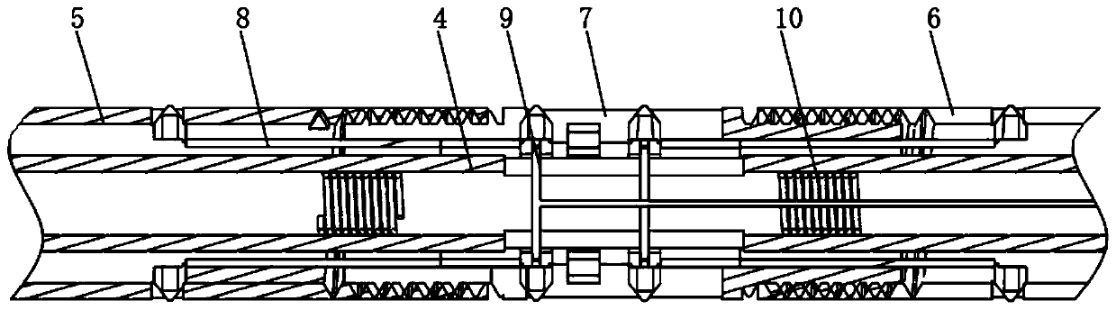
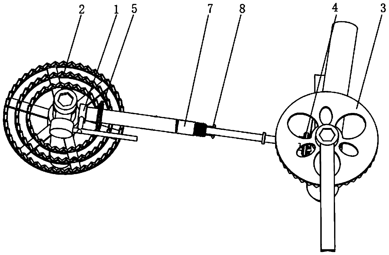
[0023] see Figure 1-7 , a shaft transmission structure of a variable speed bicycle, comprising a vehicle frame 1, a rear transmission gear 2 and a front transmission gear 3, at least two groups of gears are arranged on the rear transmission gear 2 and the front transmission gear 3, the rear transmission gear 2 and the front transmission gear The transmission gear 3 is respectively installed on the rear axle and the center axle of the vehicle frame 1, and a co...


PUM


Abstract

The invention relates to the technical field of bicycles, and discloses a shaft transmission structure of a variable-speed bicycle. The structure comprises a frame, a rear transmission gear and a front transmission gear, and at least two groups of gears are arranged on each of the rear transmission gear and the front transmission gear. According to the shaft transmission structure of the variable-speed bicycle, during assembling, the rear transmission shaft sleeve and the front transmission shaft sleeve can move respectively, the motor is meshed with the rear transmission gear and the front transmission gear in sequence without interference, the requirement on the matching precision is greatly reduced, production and assembly difficulties are reduced, ordinary people can also assemble andsimply maintain, and it is convenient to be widely applied; when the gear on one side is excessively abraded, only the abraded gear needs to be replaced, the whole gear does not need to be replaced, the use cost is reduced, the middle shaft and the rear shaft can change the speed, multi-stage speed changing is achieved through the simple structure, weight distribution is uniform, the structure islight, riding is relatively easy, and the speed changing structure is simple, convenient to maintain and high in reliability.

Description

technical field [0001] The invention relates to the technical field of bicycle equipment, in particular to a shaft transmission structure of a variable-speed bicycle. Background technique [0002] There are two kinds of transmission methods for bicycles: chain drive and shaft drive. Although the chain drive is basically popular in the market, the application of shaft drive is relatively small. However, due to the high reliability and high transmission efficiency of shaft drive, it has been developing. [0003] Although the gear transmission has a relatively high transmission ratio, it also requires high precision, while the long axis of the shaft-driven bicycle is connected to the center shaft and the rear shaft at the same time, which requires higher matching precision, which increases the difficulty of production and assembly. Difficulty, in particular, due to high assembly requirements, it is difficult for non-professionals to assemble and maintain it, which restricts the...

Claims


Application Information

Patent Timeline
Patent Type & Authority Applications(China)
IPC IPC(8): B62M17/00B62M11/00
CPCB62M11/00B62M17/00
Inventor 左刚
Owner 兰溪市驰航机械股份有限公司
Why Eureka
Try Eureka