Supercharge Your Innovation With Domain-Expert AI Agents!

Iron ingot transport box

A technology for transferring boxes and boxes, which is applied in the directions of transportation and packaging, containers, packaging, etc., can solve the problem that the automatic loading and unloading of iron ingots cannot be realized.

Pending Publication Date: 2020-05-19
正阳县华星机械有限公司
View PDF0 Cites 0 Cited by
  • Summary
  • Abstract
  • Description
  • Claims
  • Application Information

AI Technical Summary

Problems solved by technology

[0004] The purpose of the present invention is to provide an iron ingot transfer box, which is used to solve the problem that the existing transfer device cannot realize the automatic loading and unloading of iron ingots

Method used


Image

  • Iron ingot transport box
  • Iron ingot transport box
  • Iron ingot transport box

Examples


Embodiment Construction

[0022] Hereinafter, the present invention will be described in detail with reference to the drawings and examples. It should be noted that, in the case of no conflict, the embodiments of the present invention and the features in the embodiments can be combined with each other.

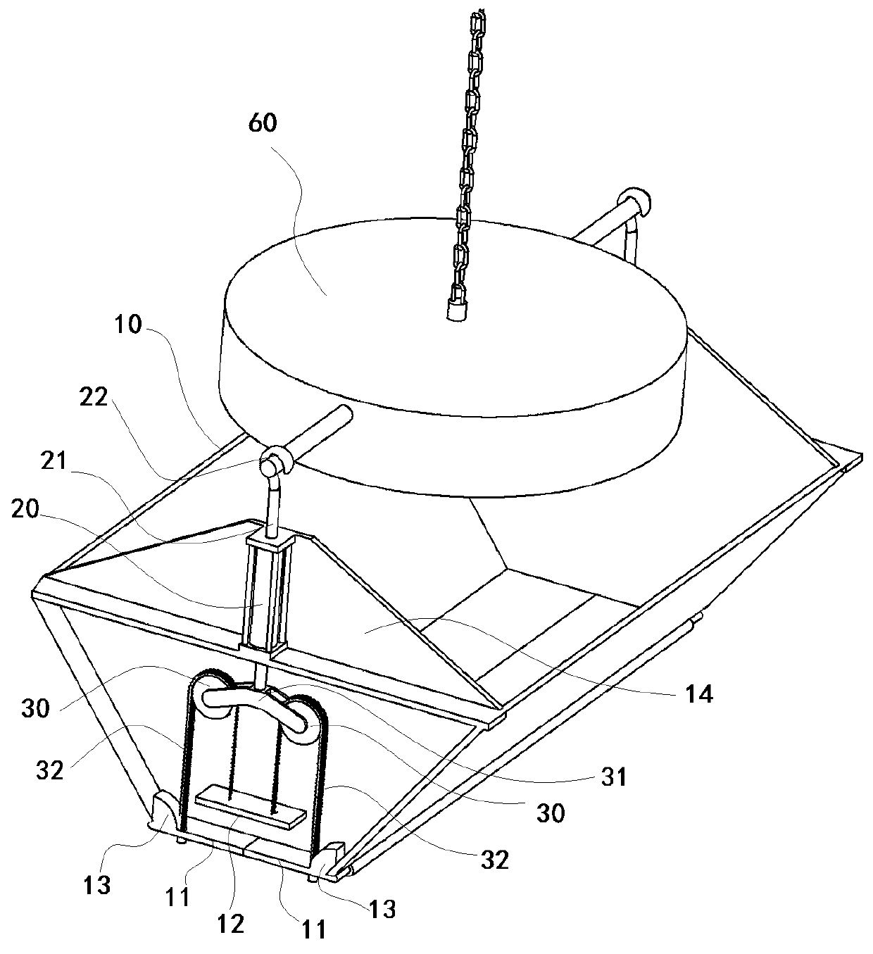
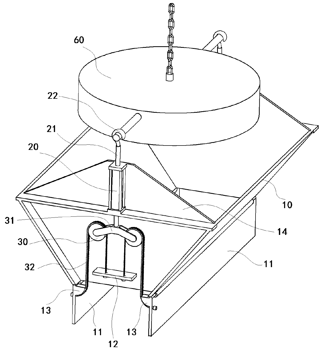
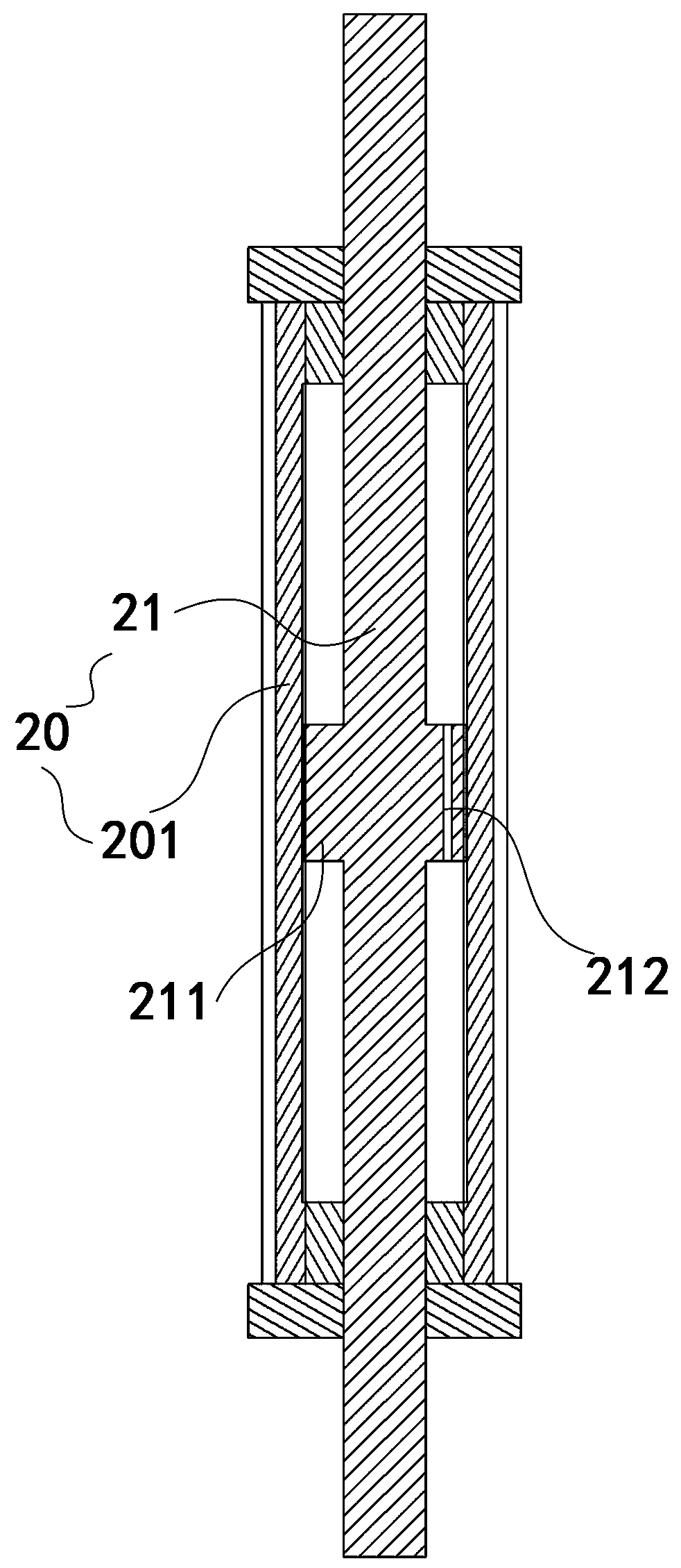
[0023] Such as Figure 1 to Figure 6 In one embodiment of the iron ingot transfer box of the present invention shown, the iron ingot transfer box of this embodiment includes a box body 10 with openings on the upper and lower parts, and two openable and closable boxes are hinged at the bottom of the box body 10 The movable door 11 of the lower opening of the box body 10 is provided with a lifting self-locking device connected with the movable door 11 respectively. The lifting self-locking device includes a damping cylinder 20 fixed on the end of the casing 10, and the damping cylinder The upper end of the piston rod 21 of 20 is provided with a lifting hook 22, and the lower end of the piston rod 21 of ...


PUM


Abstract

The invention relates to an iron ingot transport box. Two movable doors capable of opening and closing a lower opening of a box body are hinged to the bottom of the box body; lifting self-locking devices connected with the movable doors are respectively arranged at the two ends of the box body; each lifting self-locking device comprises a damping oil cylinder, a pulley support, pulleys and hinges;and the hinges can drive the movable doors to close the lower opening of the box body when the pulleys move upwards along with piston rods. According to the iron ingot transport box, the lifting self-locking devices are arranged, and when the iron ingot transport box is transported through lifting hooks, the hinges can drive the movable doors to close the lower opening of the box body, and the self-locking of the movable doors of the lower opening of the box body is realized by utilizing the weight of the box body and iron ingots in the box body in the lifting process, so that the lower opening of the box body is reliably closed; and when upward lifting acting force of the lifting hooks disappears, the gravity of the iron ingots in the box body acts on the movable doors, so that the movable doors drive the pulleys, the pulley supports and the piston rods to move downwards through the hinges, and the movable doors automatically swing downwards to open to realize automatic discharging.

Description

technical field [0001] The invention relates to casting production equipment, in particular to an iron ingot transfer box. Background technique [0002] Lost foam casting (also known as solid casting) is to bond and combine paraffin or foam models similar in size and shape to castings to form a model cluster. After brushing refractory paint and drying, it is buried in dry quartz sand for vibration molding. Down pouring, the model is vaporized, the liquid metal occupies the position of the model, solidified and cooled to form a new casting method. Lost Foam Casting is a new technology with nearly no allowance and precise molding. This technology does not need to take molds, has no parting surface, and no sand core, so the casting has no flash, burr, and draft angle, and reduces the risk of damage caused by the core. The dimensional error caused by the combination and the high surface quality of the casting can greatly reduce the cost of machining. Compared with the tradition...

Claims


Application Information

Patent Timeline
IPC IPC(8): B65D88/26B65D90/00B65D88/54
CPCB65D88/26B65D88/546B65D90/00B65D90/008
Inventor 张卫民陈霖雷志峰
Owner 正阳县华星机械有限公司
Features
  • R&D
  • Intellectual Property
  • Life Sciences
  • Materials
  • Tech Scout
  • Unparalleled Data Quality
  • Higher Quality Content
  • 60% Fewer Hallucinations
Learn More