

Feeding and discharging equipment
A technology of equipment and processing equipment, applied in the direction of conveyors, mechanical conveyors, conveyor objects, etc., can solve the problems of low degree of automation and low efficiency of tool loading and unloading
- Summary
- Abstract
- Description
- Claims
- Application Information
AI Technical Summary
Problems solved by technology
Method used
Image

Examples
Embodiment Construction
[0008] Embodiments of the present invention are described in detail below, and by referring to the attached Figure 1-34 The described embodiments illustrate the invention, but reference is made to the appended Figure 1-34 The content shown in should not be construed as limiting the present invention.
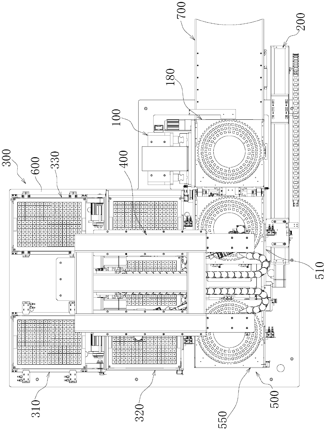
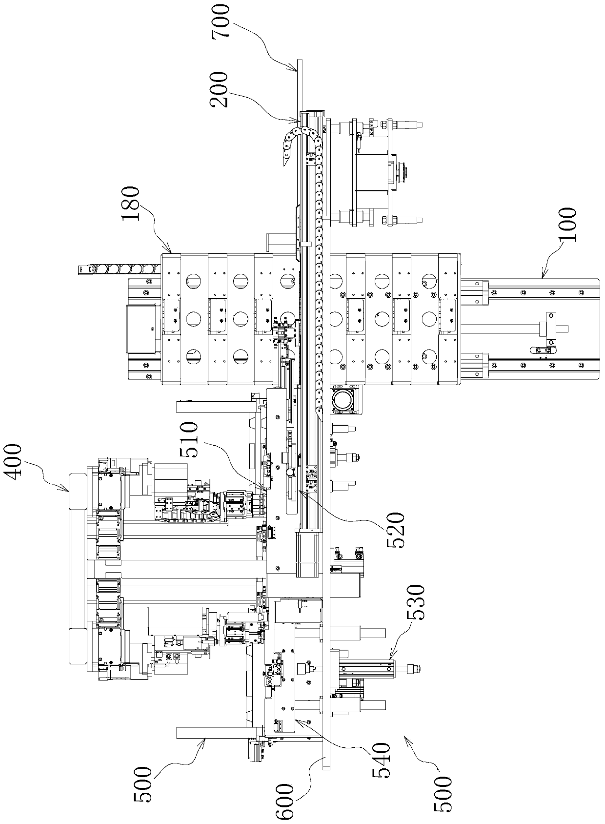
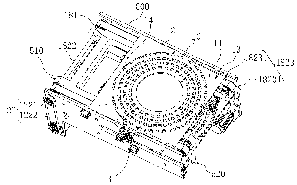
[0009] Such as Figure 1-34 As shown, in one embodiment of the present invention, a kind of loading and unloading equipment is provided, which is used in conjunction with processing equipment. The processing equipment is mainly used for grinding tools or passivating tools. The tools can be indexable tools, milling cutters, drills Wait.
[0010] The loading and unloading equipment: includes a frame 600, a carrier circulation device 500, a jig manipulator 200, a tray circulation device 300 and a tool loading and unloading device 400; the carrier circulation device 500 is installed on the frame 600, and the carrier circulation device 500 The carrier 1 for carrying the jig 2 ba...
PUM
 Abstract
Description
Claims
Application Information