A smart lock structure

A technology of smart locks and lock casings, applied in the field of locks, can solve problems such as difficult imaging, affecting the use of locks, and fewer fingerprints and fingerprints, and achieve the effects of novel and practical design, prolonging service life, and improving security

Active Publication Date: 2021-04-30
ZHEJIANG DINGLI IND
View PDF6 Cites 0 Cited by
  • Summary
  • Abstract
  • Description
  • Claims
  • Application Information

AI Technical Summary

Problems solved by technology

[0004] The disadvantage of fingerprint combination locks is that some people or some groups have few fingerprints and fingerprints, which are difficult to image; every time a fingerprint is used, the user's fingerprint will be left on the fingerprint collection head, and these fingerprints are used to copy fingerprints. Possibility; stability and durability are not as strong as mechanical passwords; many fingerprint recognitions cannot be unlocked with wet hands due to technical and cost constraints
The disadvantage of password unlocking is that you need to change the password frequently to ensure security, but this will cause you to often forget the password; even if it is a fake password, if you enter it as it is, you can still open the door
[0005] The existing smart lock structure mainly adopts the motor-driven door bolt mode, and its technical defect is that the motor drive system is always connected to the door bolt, and the failure rate is high. On the one hand, it affects the use of the lock, and on the other hand, the service life is short. Structure can solve problems

Method used


Image

  • A smart lock structure
  • A smart lock structure
  • A smart lock structure

Examples


Embodiment Construction

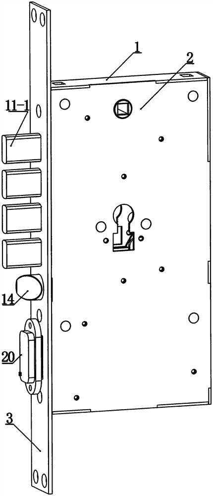
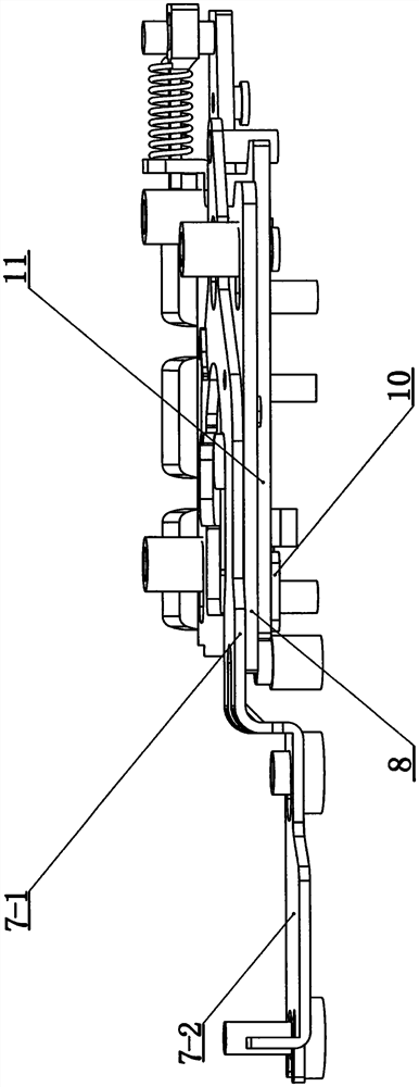
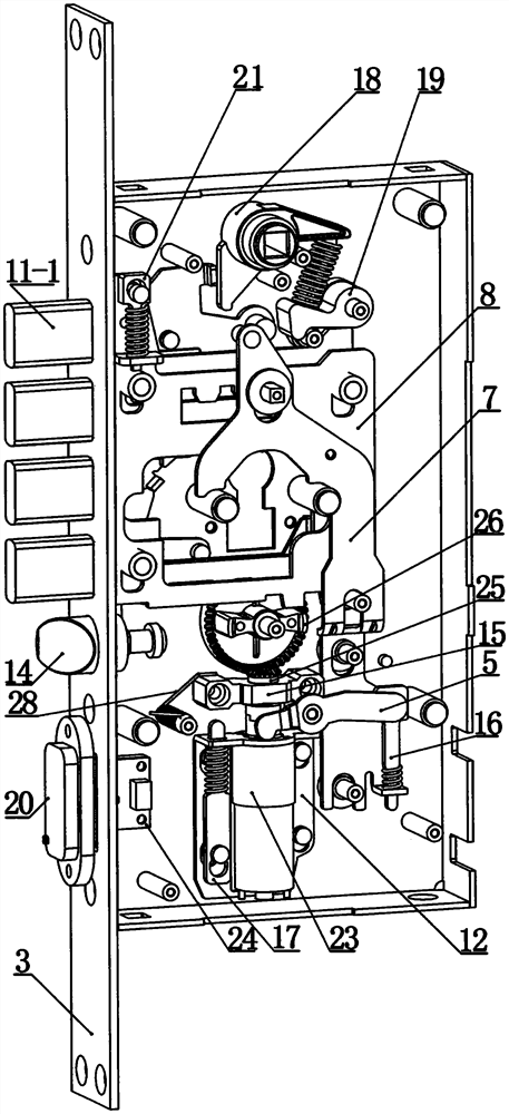
[0028] Such as figure 1It is a schematic diagram of the appearance of the present invention, reflecting the lock case 1, the bottom plate 2, the side plate 3, the oblique tongue 14, the electromagnetic block 20 and the four parallel bolts 11-1 connected to the top of the bolt plate 11, the lock case 1, the bottom plate 2 There are several installation holes or grooves, positioning columns or positioning pins respectively on the side plate 3, and the lock housing 1 and the bottom plate 2 can form a cavity, and the side plate 3 is vertically attached to the left side of the cavity, and in the cavity Panel 4, buckle 5, pull plate 6, fixed plate 7, clamp plate 8, push plate 9, slot plate 10, bolt plate 11, motor fixing part 12, rack plate 13, fixing part 15, fixed Pin 16, motor buffer pin 17, shift fork 18, dial sleeve 19, clamp pin 21, circuit board 22, motor 23, electromagnetic induction part 24, helical gear 25, gear push block 26, coil spring 27 and torsion spring 28, The dea...


PUM


Abstract

The invention relates to the technical field of locks, and relates to an intelligent lock structure, including a lock case, a bottom plate, a side plate, a panel, a buckle, a pull plate, a fixed plate, a clamp plate, a push plate, a slot plate, a bolt plate, and a motor fixing piece , rack plate, oblique tongue, fixed piece, fixed pin, motor buffer pin, shift fork, dial sleeve, electromagnetic block, clamp pin, circuit board, motor, electromagnetic induction part, helical gear, gear push block, coil spring and The torsion spring, the lock case, the bottom plate and the side plate can form a cavity, which has a four-layer structure at the upper middle of the cavity. On the second floor, the position of the deadbolt plate is the third floor, and the position of the card slot plate and the rack plate is the fourth floor. The door is locked by electromagnetic induction, the door is opened by the finger vein recognition head, and the switch of the motor is controlled by the finger vein technology. , The motor drives the lock bolt telescopic mechanism, avoiding the direct connection between the motor and the door bolt, prolonging the service life of the lock and improving the security of the smart lock.

Description

technical field [0001] The invention relates to the technical field of locks, in particular to an intelligent lock structure that controls the switch of a motor through finger vein technology and drives a bolt retractable mechanism through a gear. Background technique [0002] The current locks mainly include traditional mechanical locks and new smart locks, while the smart locks on the market now mainly include combination locks and fingerprint locks. There is a row of holes on the rotating inner shaft of the traditional mechanical lock, and there are small copper pillars inside, and a corresponding row of small holes and a row of copper pillars are also placed on the lock body that matches the inner shaft. It is relatively short, so the copper casting on the inner wall is inserted into the inner shaft, so that the inner shaft cannot rotate. When the corresponding key is inserted, the copper column and the teeth on the key contact to form a regular curve. Lift up the coppe...

Claims


Application Information

Patent Timeline
Patent Type & Authority Patents(China)
IPC IPC(8): E05B63/14E05B47/00E05B15/00E05B17/20G07C9/30
CPCE05B17/20E05B47/0001E05B47/0002E05B47/0012E05B63/146E05B2047/002E05B2047/005G07C9/00563
Inventor 俞云祥陆勇星刘勇灿谢妃潘伟华
Owner ZHEJIANG DINGLI IND
Why Eureka
Try Eureka