High-low temperature alternating pure metal two-way sealing ball valve

A technology of two-way sealing ball valve and metal sealing ring, applied in valve details, valve device, valve shell structure, etc., can solve the problems of high production cost and maintenance cost, complex sealing structure, and many parts, so as to improve service life cycle, Improved wear resistance and high sealing performance

Pending Publication Date: 2020-05-19
SICHUAN SUKE FLUID CONTROL EQUIP CO LTD
View PDF1 Cites 2 Cited by
  • Summary
  • Abstract
  • Description
  • Claims
  • Application Information

AI Technical Summary

Problems solved by technology

[0010] The purpose of the present invention is to provide a high and low temperature alternating pure metal two-way sealed ball valve, which solves the above-mentioned technical problems of the existing high and low temperature alternating ball valve, such as complicated sealing structure, numerous parts, high production cost and high maintenance cost. question

Method used


Image

  • High-low temperature alternating pure metal two-way sealing ball valve
  • High-low temperature alternating pure metal two-way sealing ball valve
  • High-low temperature alternating pure metal two-way sealing ball valve

Examples


Embodiment 1

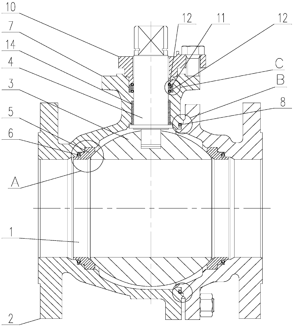
[0059] Such as Figure 1 to Figure 9 As shown, a high and low temperature alternating pure metal two-way sealed ball valve of the present invention includes a valve body 2 provided with a valve cavity 1, a ball 3 located in the valve cavity 1 and sealingly matched with the valve cavity 1 through a valve seat sealing pair, the The top of the sphere 3 is connected to the valve stem 4, preferably the valve stem 4 is flatly connected to the sphere 3. After the sphere is closed, the valve stem 4 does not bear the thrust of the medium in the valve cavity 1; Neck, the top of the valve stem 4 passes through the neck, and cooperates with the rotation and sealing of the neck. Manually or using a driving device to drive the valve stem 4 to rotate, so as to drive the ball 2 to rotate around the axis of the valve stem 4, so that the ball 2 Rotate within the range of 90° to realize the switch of the flow channel of the ball valve; there are two valve seat sealing pairs, which are respective...

Embodiment 2

[0069] This embodiment is based on Embodiment 1, and describes the specific implementation structure of the spring-compensated metal sealing ring A6.

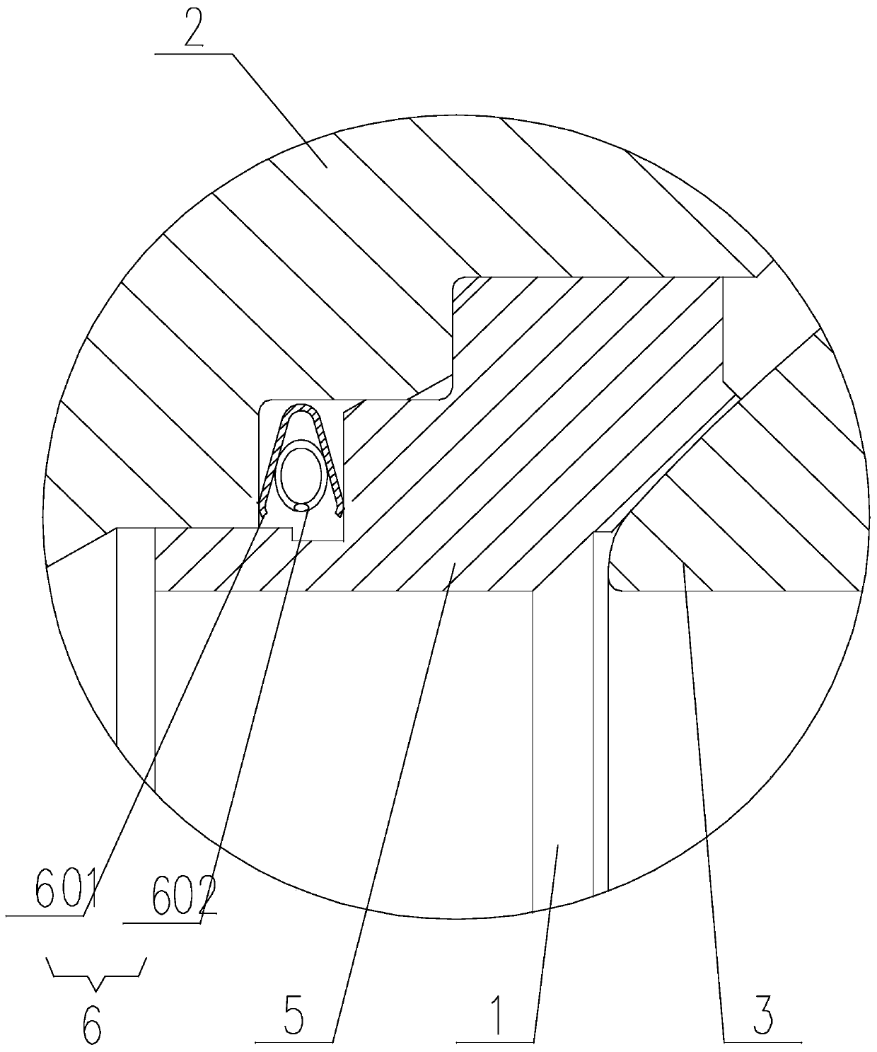
[0070] Such as figure 1 , figure 2 , Figure 5 , Figure 8 as well as Figure 9 As shown, in the present invention, the spring compensation type metal sealing ring A6 includes an outer elastic metal ring A601 and an inner compensation spring ring A602 whose axes both coincide with the axis of the flow channel, and the cross section of the outer elastic metal ring A601 is V shape, preferably its V-shaped opening faces the axis of the flow channel, and its two sides are respectively in contact with the end of the shaft shoulder and the bottom of the matching hole. The inner compensation spring ring A602 is installed on the outer elastic metal ring A601 In the V-ring groove, and in contact with the groove walls on both sides of the V-ring groove.

[0071] In the present invention, the unique structural design of the valve se...

Embodiment 3

[0076] This embodiment is based on the above-mentioned embodiments, to further illustrate the structure of the valve body 2 .

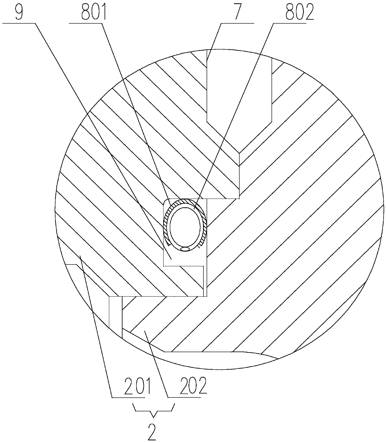
[0077] Such as figure 1 As shown, in the present invention, the valve body 2 is divided into a left valve body 201 and a right valve body 202 by a plane perpendicular to the axis of the flow channel, and the valve cavity 1 is correspondingly divided into a left valve cavity and a right valve body located on the left valve body 201. The right valve chamber located on the right valve body 202, the ball center of the sphere 3 is located in the left valve chamber, and the top of the left valve body 201 protrudes into a neck 7 that is sealingly matched with the valve stem 4;

[0078] The left valve body 201 is detachably connected to the right valve body 202 through fasteners, and a spring is arranged between the left valve body 201 and the right valve body 202 to seal the divided parts of the left valve body 201 and the right valve body 202 Compensation ...


PUM


Abstract

The invention discloses a high-low temperature alternating pure metal two-way sealing ball valve. The high-low temperature alternating pure metal two-way sealing ball valve comprises a valve body provided with a valve cavity, and a ball body located in the valve cavity and in sealing fit with the valve cavity through a valve seat sealing pair, the top of the ball body is connected with a valve rod, and the valve seat sealing pair comprises an annular valve seat; a plurality of shaft shoulders are arranged on the outer circumferential wall of the valve seat, and the side, close to the ball body, on the inner wall of the valve seat is tangent to the ball body; and a flowing channel transits onto the valve cavity through N-stages step holes, the N shaft shoulder is inserted into an Nhole body, a spring compensation type metal sealing ring A is arranged between the N shaft shoulder and the N hole body, and the spring compensation type metal sealing ring A is at least in apressed state in the direction parallel to the axis of the flowing channel. According to the high-low temperature alternating pure metal two-way sealing ball valve, floating sealing is achieved through the sealing ring with an elastic compensation function, size compensation required by temperature change is met, whether the high temperature, the low temperature or high-low temperature alternating, high-temperature expansion deformation and low-temperature shrinkage deformation are overcome, and tight sealing of the ball valve in various changing work conditions can be effectively ensured.

Description

technical field [0001] The invention relates to the technical field of ball valves, in particular to a high-low temperature alternating pure metal two-way sealing ball valve. Background technique [0002] Ball valves have good flow capacity and sealing performance, and their valves are widely used in petroleum, petrochemical, chemical, energy, mining and other industries. The ball valve mainly includes a ball as a valve core, a valve stem that drives the ball to rotate, and a valve body that seals with the ball through a valve seat sealing pair. The ball is provided with a fluid channel perpendicular to its axis of rotation. With the change of the production process of the working conditions of the ball valve, the utilization rate of the ball valve is improved, and the working conditions of the ball valve are becoming more and more harsh, which is mainly reflected in high temperature, low temperature and high and low temperature alternation. For these harsh working conditio...

Claims


Application Information

Patent Timeline
Patent Type & Authority Applications(China)
IPC IPC(8): F16K5/20F16K5/06F16K27/06
CPCF16K5/0657F16K5/0694F16K5/201F16K27/067
Inventor 李威张小强段伟李勇张道军
Owner SICHUAN SUKE FLUID CONTROL EQUIP CO LTD
Why Eureka
Try Eureka