
Tension tester for pre-twisted hardware fitting

A tensile testing machine and hardware technology, which is applied in the direction of applying stable tension/pressure to test the strength of materials, measuring devices, instruments, etc., can solve the lack of buffer mechanism and protection mechanism of the testing device, and the clamping of pre-twisted hardware is not firm, etc. problems, to achieve the effect of improving safety, improving practical convenience, and prolonging practical life.

Active Publication Date: 2020-05-19
JIANGSU HUAMAI NEW MATERIAL CO LTD
View PDF13 Cites 5 Cited by
  • Summary
  • Abstract
  • Description
  • Claims
  • Application Information

AI Technical Summary

Problems solved by technology

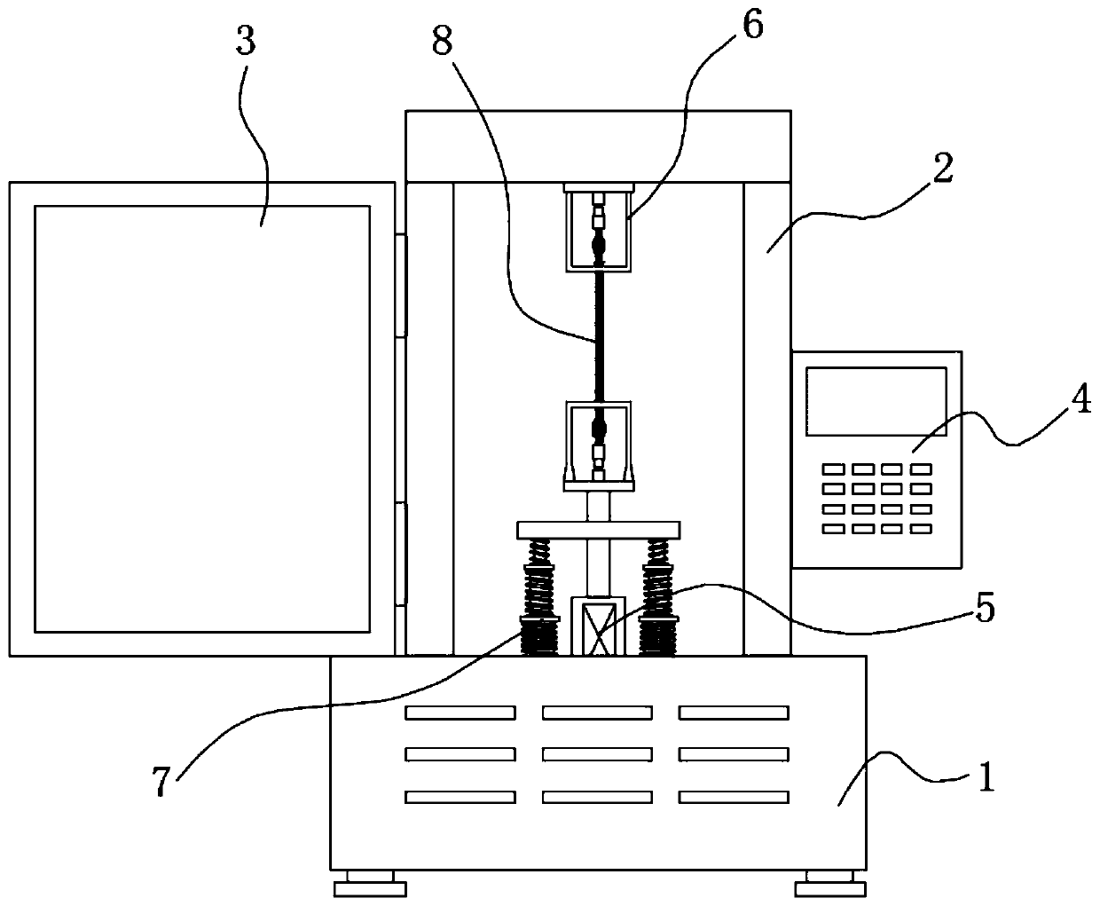
[0004] The purpose of the present invention is to solve the shortcomings of the pre-twisted metal fittings in the prior art that the clamping is not firm and the test device lacks a buffer mechanism and a protective mechanism, and proposes a tensile testing machine for pre-twisted metal fittings

Method used


Image

  • Tension tester for pre-twisted hardware fitting
  • Tension tester for pre-twisted hardware fitting
  • Tension tester for pre-twisted hardware fitting

Examples


Embodiment 1

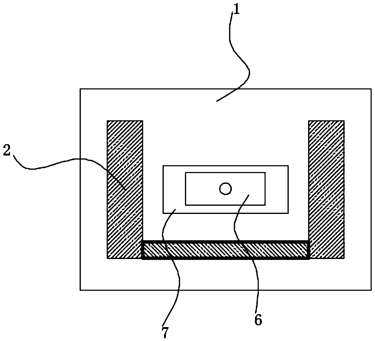
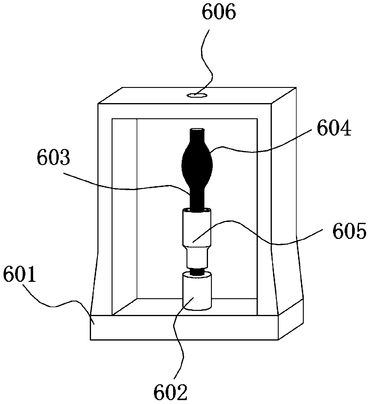
[0029] refer to Figure 1-5 , this embodiment relates to a tensile testing machine for pre-twisted metal fittings, comprising a base 1, a support frame 2, a protective door body 3 and a control device 4, the support frame 2 is fixedly installed on the base 1, and the control device 4 is fixedly installed on the support One side of the frame 2, the front side of the support frame 2 is equipped with a protective door body 3 by a hinge, the middle part of the base 1 is fixedly installed with a tension hydraulic rod 5 vertically facing the inside of the support frame 2, the piston rod upper end of the tension hydraulic rod 5 and The top of the support frame 2 is respectively equipped with corresponding test fixtures 6, the base 1 is located at the tension device 5 and equipped with a buffer protection mechanism 7, and a locking mechanism is arranged between the support frame 2 and the protective door body 3, the locking mechanism is Pins and pin holes.

[0030] The test fixture 6...

Embodiment 2

[0037] refer to Figure 1-4, 6. The difference between this embodiment and the first embodiment is that the implementation of the buffer protection mechanism 7 is different. The second support rod 704 is a telescopic structure formed by connecting multiple groups of rod bodies in sequence. The base 1 on both sides of the tension hydraulic rod 5 is relatively telescopically equipped with a telescopic support rod 2 704, and the buffer plate 701 is fixedly installed on the two telescopic support rods 2 704. The upper end of each rod body of the telescopic support rod 2 704 is equipped with a buffer spring 2 705, and the middle part of the buffer plate 701 is provided with a through hole 606, and the piston rod of the tension hydraulic rod 5 passes through and is fixedly installed with a test fixture. 6. The elastic coefficient of the buffer spring 2 705 outside the telescopic support rod 2 704 increases sequentially from top to bottom.

[0038] In this embodiment, the telescopic...


PUM


Abstract

The invention discloses a tension tester for a pre-twisted hardware fitting. The invention relates to the field of pre-twisted fittings. The tester comprises a base, a supporting frame, a protective door body and a control device. The supporting frame is fixedly installed on the base. The control device is fixedly installed on one side of the supporting frame. A protective door body is mounted onthe front side of the supporting frame through a hinge; a tension hydraulic rod vertically facing the interior of the supporting frame is fixedly installed in the middle of the base, correspondingly-arranged test clamps are installed at an upper end of a piston rod of the tension hydraulic rod and the top of the supporting frame respectively, and a buffer protection mechanism is installed at the position, located at a tension device, of the base. According to the invention, the test fixture which is conveniently connected with the pre-twisted hardware fitting is arranged, the convenience degree of the test and installation of the pre-twisted hardware fitting is improved, the buffer protection mechanism can buffer and unload the tension, protect the tension hydraulic rod which generates thetension, prevent the tension hydraulic rod from being damaged due to instantaneous counter tension, and prolong the service life of the device.

Description

technical field [0001] The invention relates to the field of pre-twisted metal fittings, in particular to a tensile testing machine for pre-twisted metal fittings. Background technique [0002] Pre-twisted fittings refer to fittings that are wound with preformed helical strips on wires or ground wires to withstand mechanical or electrical loads. Pre-twisted fittings were invented by the American PLP company in the 1940s. For decades, pre-twisted fittings have been successfully used in many high-voltage lines abroad. my country's pre-twisted fittings have been used since the 1980s, and are mainly used in all-dielectric self-supporting optical fiber cable (ADSS), optical fiber composite overhead ground wire (optical fiber composite overhead wire, OPGW) optical cable and UHV power transmission line project. [0003] Grip testing of pre-twisted fittings is an important part of fitting performance. Therefore, whether its performance meets the standard is related to the safety o...

Claims


Application Information

Patent Timeline
Patent Type & Authority Applications(China)
IPC IPC(8): G01N3/10G01N3/04G01N3/02
CPCG01N3/02G01N3/04G01N3/10G01N2203/0017G01N2203/0048G01N2203/04
Inventor 周兴华孙飞桑清华吴小龙蔡小锋刘军
Owner JIANGSU HUAMAI NEW MATERIAL CO LTD
Learn More