High-density optical fiber array structure

An optical fiber array, high-density technology, applied in the field of optical fiber array, can solve the problems of cumbersome operation and heavy workload, and achieve the effect of simple operation

Pending Publication Date: 2020-05-19
苏州易缆微光电技术有限公司
View PDF0 Cites 0 Cited by
  • Summary
  • Abstract
  • Description
  • Claims
  • Application Information

AI Technical Summary

Problems solved by technology

[0002] In the existing optical fiber array, when the left part of the optical fiber is stripped and then positioned and placed, the optical fiber is usually arranged one by one manually, which is cumbersome and heavy workload. Therefore, a high-density optical fiber array structure is needed to solve the above problems

Method used


Image

  • High-density optical fiber array structure
  • High-density optical fiber array structure
  • High-density optical fiber array structure

Examples


Embodiment Construction

[0018] In order to make the technical means, creative features, goals and effects achieved by the present invention easy to understand, the present invention will be further described below in conjunction with specific embodiments.

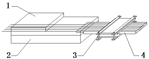
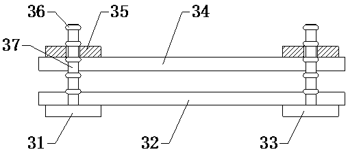
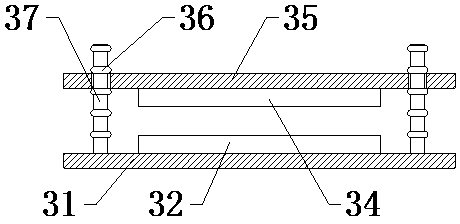
[0019] see Figure 1-Figure 5 , the present invention provides a technical solution: a high-density optical fiber 4 array structure, including an upper substrate 1, a lower substrate 2 is placed under the upper substrate 1, an optical fiber 4 is arranged between the upper substrate 1 and the lower substrate 2, and the optical fiber 4 passes through the clip The clamping mechanism 3, the clamping mechanism 3 is placed on the right side of the upper substrate 1 and the lower substrate 2, the user removes the coating of the optical fiber 4 from the left part of the optical fiber 4, and then places the bare part of the optical fiber 4 on the V-shaped groove 5 on the lower substrate, Then apply adhesive on the lower substrate 2 , and then stamp the upp...


PUM


Abstract

The invention provides a high-density optical fiber array structure. The structure comprises a left connecting plate, a lower rubber pad, a right connecting plate, an upper rubber pad, clamping plates, O-shaped rings and positioning rods, the left connecting plate and the right connecting plate are adhered and fixed at a left part and a right part of a lower end surface of the lower rubber pad; the clamping plates are adhered to and fixed at left and right parts of the upper end surface of the upper rubber pad; the positioning rods are fixed at the upper ends of the left connecting plate and the right connecting plate; the positioning rods are arranged on a front side and a rear side of the lower rubber pad respectively; the O-shaped ring is embedded and fixed on an annular side surface ofeach positioning rod; and the positioning rods penetrate through the clamping plates upwards, and the O-shaped rings are arranged on the upper side and the lower side of the clamping plates. Comparedwith the prior art, by using the structure of the invention, there are the following advantages that optical fibers can be conveniently clamped and fixed side by side so that optical fibers can be conveniently positioned and placed by personnel; and operation is simple, and the optical fibers can be conveniently protected through the upper rubber pad and the lower rubber pad.

Description

technical field [0001] The invention relates to a high-density optical fiber array structure, which belongs to the field of optical fiber arrays. Background technique [0002] In the existing optical fiber array, when the left part of the optical fiber is stripped and then positioned and placed, the optical fiber is usually arranged one by one manually, which is cumbersome and heavy workload. Therefore, a high-density optical fiber array structure is needed to solve the above problems. Contents of the invention [0003] Aiming at the deficiencies in the prior art, the purpose of the present invention is to provide a high-density optical fiber array structure to solve the problems raised in the above-mentioned background technology. The optical fiber is positioned and placed. [0004] In order to achieve the above object, the present invention is achieved through the following technical solutions: a high-density optical fiber array structure, including an upper substrate,...

Claims


Application Information

Patent Timeline
IPC IPC(8): G02B6/36
CPCG02B6/3608G02B6/3636
Inventor 王世群陈伟
Owner 苏州易缆微光电技术有限公司
Why Eureka
Try Eureka