Bone conduction loudspeaker and composite loudspeaker

A technology of bone conduction speakers and speakers, applied in the field of speakers, can solve the problems of air conduction speakers, single speakers, and single air conduction speakers, and achieve good high-frequency performance, small size, and excellent bass performance. Effect

Pending Publication Date: 2020-05-19
深圳市创想听力技术有限公司
View PDF0 Cites 6 Cited by
  • Summary
  • Abstract
  • Description
  • Claims
  • Application Information

AI Technical Summary

Problems solved by technology

[0004] The purpose of the present invention is to provide a bone conduction speaker and a composite speaker, aiming at solving the problem that the speaker in the prior art is a single air conduction speaker or a single bone conduction speaker, and cannot have both an air conduction speaker and a bone conduction speaker The technical aspects of the merits of these two speakers

Method used


Image

  • Bone conduction loudspeaker and composite loudspeaker
  • Bone conduction loudspeaker and composite loudspeaker
  • Bone conduction loudspeaker and composite loudspeaker

Examples


Embodiment 1

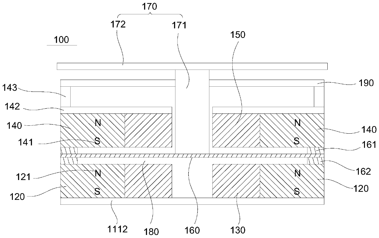
[0039] A bone conduction speaker 100 in this embodiment includes a bottom plate 1112 , a lower magnet 120 , a lower coil 130 , an upper magnet 140 , an upper coil 150 , a vibrating piece 160 , a centering strut 190 and a conductive piece 170 . The lower magnet 120 is fixed on the bottom plate 1112 . The lower coil 130 is disposed around the inner side of the lower magnet 120 . The upper magnet 140 is fixed above the lower magnet 120 . The lower magnet 120 is separated from the upper magnet 140 , and a first magnetic gap 180 is formed between them. The two magnetic poles on the upper and lower sides of the first magnetic gap 180 are mutually different poles. In this embodiment, the two magnetic poles are the S magnetic pole 141 of the upper magnet 140 and the N magnetic pole 121 of the lower magnet 120 respectively. The upper coil 150 is disposed around the inner side of the upper magnet 140 , and a through hole is formed in the upper coil 150 . The vibrating piece 160 is su...

Embodiment 2

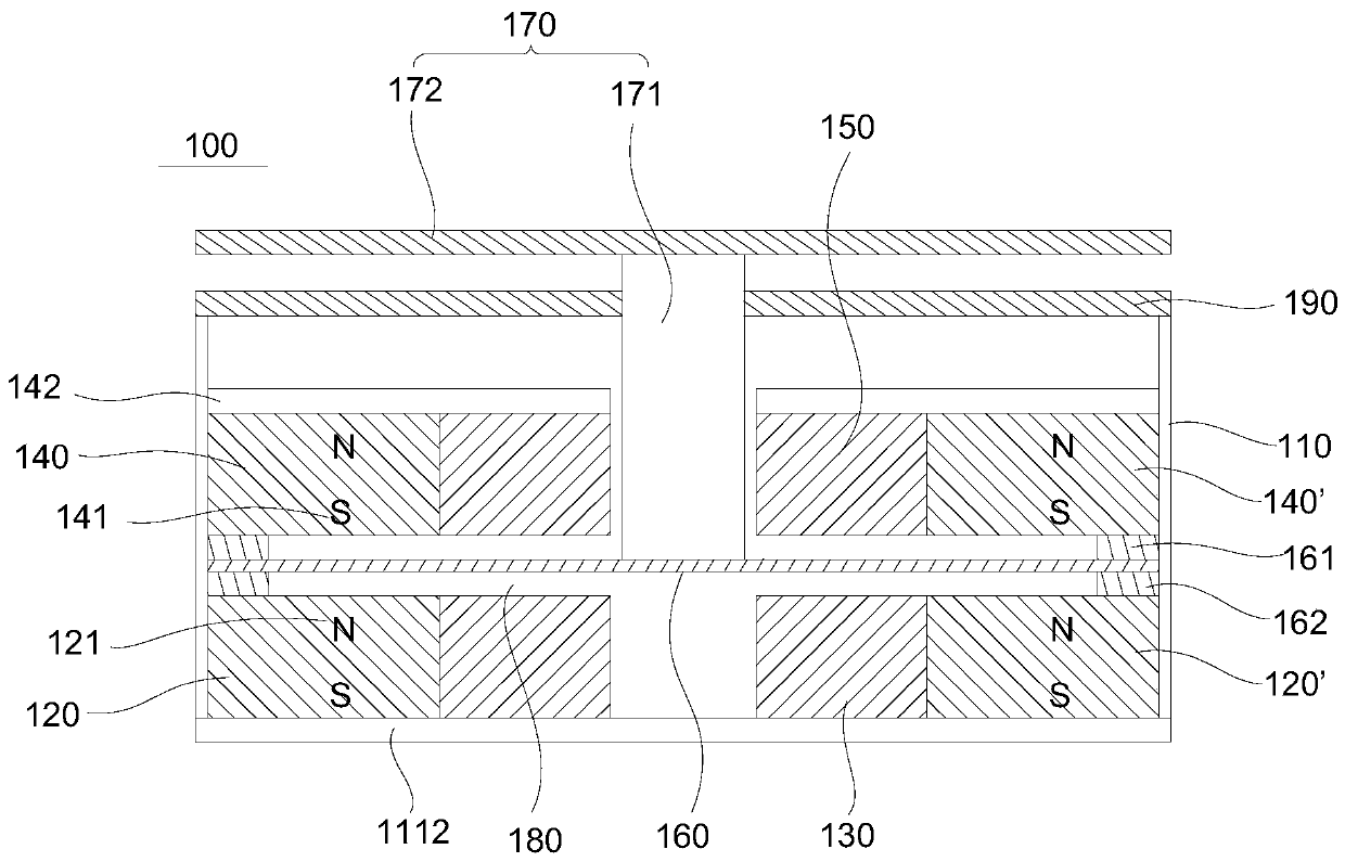
[0049] see figure 2 The difference between this embodiment and Embodiment 1 is that: the bone conduction speaker 100 further includes a first housing 110 , and the lower magnet 120 and the upper magnet 140 are housed in the first housing 110 . The first shell 110 plays a supporting role. The damper 190 is an elastic supporting component. The vibrating piece 160 is a vibrating piece made of metal composite material. The vibrating piece made of metal composite material is a vibrating piece made of plastic, with a metal coating on its surface, which has the characteristics of light weight. The bottom board 1112 is a first PCB board. The power lines of the lower coil 130 and the upper coil 150 are connected to the first PCB, and the first PCB is connected to external circuits.

[0050] The top plate 142 is an extension of the housing. The shell extension is fixedly connected to the inner wall of the first shell 110 .

[0051] The upper magnets 140, 140' are strip-shaped. Th...

Embodiment 3

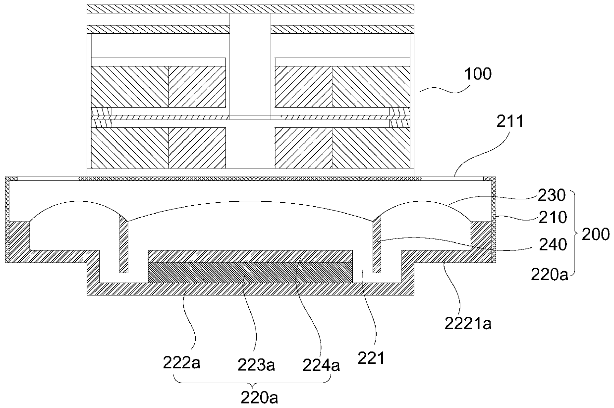
[0054] see figure 2 and image 3 , this embodiment provides a composite speaker, including the air conduction speaker 200 and the bone conduction speaker 100 provided in Embodiment 2. The bone conduction speaker 100 is fixed on the air conduction speaker 200 .

[0055] The air conduction speaker 200 includes a second housing 210 , a magnetic unit 220 a , a diaphragm 230 and a voice coil 240 . The bone conduction speaker 100 is fixed on the second housing 210 . The magnetic unit 220 is accommodated in the second housing 210 , and a second magnetic gap 221 is formed in the magnetic unit 220 . The diaphragm 230 is suspended in the second casing 210 , and its periphery is fixedly connected with the second casing 210 . The voice coil 240 is fixedly connected with the diaphragm 230 and extends into the second magnetic gap 221 .

[0056] When the air conduction speaker 200 is working, the voice coil 240 is energized to generate an electromotive force and drive the diaphragm 230...


PUM


Abstract

The invention discloses a bone conduction loudspeaker which comprises a bottom plate, a lower magnet, a lower coil, an upper magnet, an upper coil, a vibrating reed, a centering disk and a conductionpiece. The lower magnet is fixedly arranged on the bottom plate. The lower coil is annularly arranged on the inner side of the lower magnet. The upper magnet is fixedly arranged above the lower magnet. The lower magnet is separated from the upper magnet. A first magnetic gap is formed between the lower magnet and the upper magnet. Two magnetic poles on the upper and lower sides of the first magnetic gap are different magnetic poles. The upper coil is annularly arranged on the inner side of the upper magnet. A through hole is formed in the upper coil. The vibrating reed is suspended in the first magnetic gap. The periphery of the vibrating reed is fixed between the upper magnet and the lower magnet. The centering disk is fixedly arranged above the upper magnet. The conduction piece is movably arranged in the through hole. The root of the conduction piece is fixedly connected to the vibrating reed, and the top of the conduction piece penetrates through the centering disk. The invention further provides a composite loudspeaker, the composite loudspeaker comprises an air conduction loudspeaker and the bone conduction loudspeaker, and the bone conduction loudspeaker is fixedly arrangedon the air conduction loudspeaker.

Description

technical field [0001] The invention belongs to the technical field of loudspeakers, in particular to a bone conduction loudspeaker and a composite loudspeaker. Background technique [0002] Loudspeakers in the prior art are mainly classified into air conduction loudspeakers and bone conduction loudspeakers. Air-conduction speakers produce sound through the vibration of the diaphragm, which is transmitted to the human ear through air transmission. Bone conduction speakers conduct sound through the principle of bone conduction. Air conduction speakers have the advantages of high audio separation and reproduction. Bone conduction is the use of human skull, inner ear lymph, auditory nerve and other carriers to transmit sound waves, so that people can hear the sound. Using bone conduction earphones, without plugging the ears, can open the ears and reduce damage to the eardrum, and can hear the other party's voice clearly even in noisy situations. [0003] The loudspeaker in ...

Claims


Application Information

Patent Timeline
Patent Type & Authority Applications(China)
IPC IPC(8): H04R9/06H04R9/02
CPCH04R9/02H04R9/06H04R2460/13
Inventor 朱达云
Owner 深圳市创想听力技术有限公司
Why Eureka
Try Eureka