Soil ecological remediation device for industrial land

An ecological restoration and soil technology, applied in the field of soil restoration, can solve the problems of easy agglomeration and hardness of soil, inability to crush soil, serious soil pollution of industrial land, etc., and achieve the effect of sufficient mixing and improving restoration efficiency.

Active Publication Date: 2020-05-22
吉林省汇创科技有限公司
View PDF4 Cites 2 Cited by
  • Summary
  • Abstract
  • Description
  • Claims
  • Application Information

AI Technical Summary

Problems solved by technology

[0004] Due to the discharge of industrial sewage or the dumping of industrial waste, the soil pollution of industrial land is more serious. The soil of industrial land is easy to agglomerate and has hi

Method used


Image

  • Soil ecological remediation device for industrial land
  • Soil ecological remediation device for industrial land
  • Soil ecological remediation device for industrial land

Examples


Embodiment 1

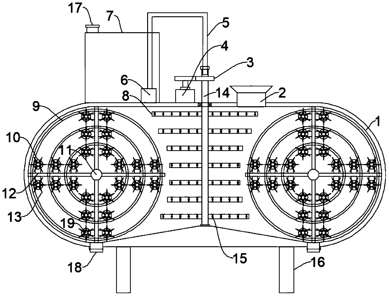
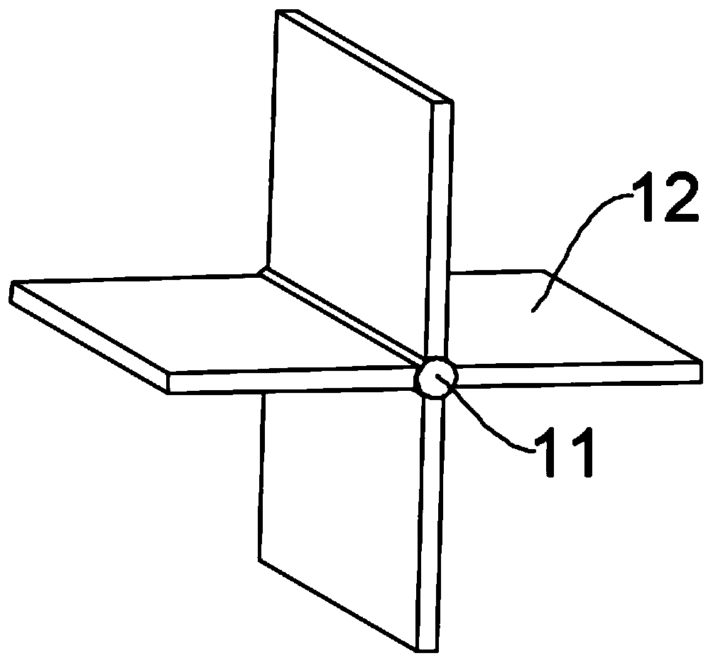
[0024] see Figure 1~2 , in an embodiment of the present invention, an industrial land soil ecological restoration device includes a box body 1, a mixing unit and a liquid supply unit, the left and right side walls of the box body 1 are in the shape of a semicircle, and the bottom of the box body 1 is evenly and symmetrically fixed and installed with Support legs 16, the top of the box body 1 is provided with a feed hopper 2, both ends of the bottom of the box body 1 are provided with a discharge port 18, and a valve is installed on the discharge port 18, and the bottom of the inner cavity of the box body 1 is from the middle to both sides. The discharge port 18 is arranged obliquely to facilitate discharging. The mixing unit includes a pulverizing mechanism and a stirring mechanism. The stirring mechanism includes a rotating shaft 14, a mixing tube 8 and a driving mechanism for driving the rotating shaft 14 to rotate. The rotating shaft 14 is installed in rotation. In the mid...

Embodiment 2

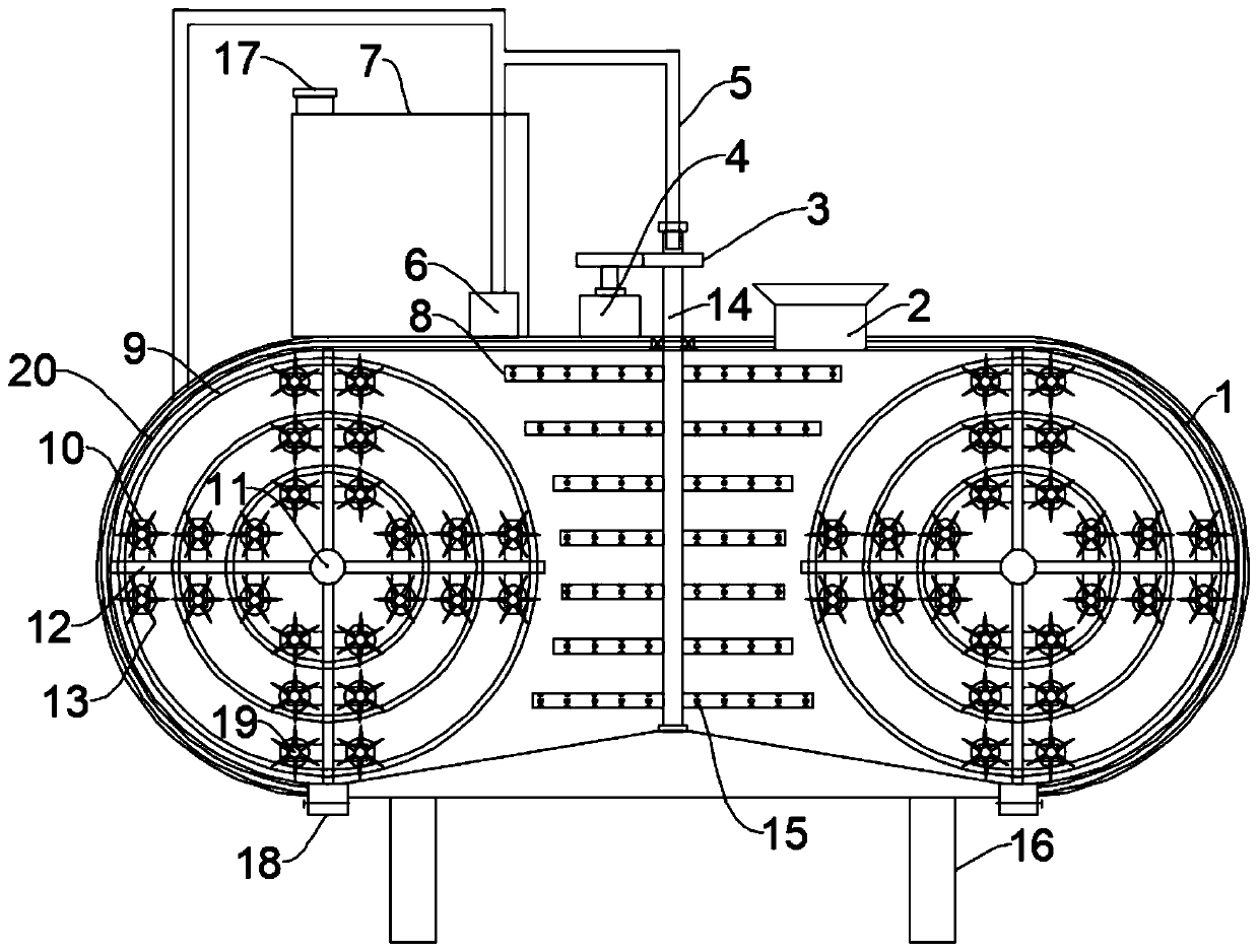
[0027] see image 3 The difference between this embodiment of the present invention and Embodiment 1 is that a liquid channel 20 is provided on the upper wall of the box body 1, and a channel communicating with the liquid channel 20 is evenly opened on the upper inner wall of the box body 1. A protective net is installed in the through hole, and the other liquid outlet pipe of the liquid supply pipeline 5 communicates with the liquid channel 20. When the soil is mixed and scattered, the repair liquid is further mixed with the soil to improve the repair efficiency.

[0028]The working principle of the present invention is: when working, the soil is added into the box body 1 from the feed hopper 2, the driving mechanism is started to drive the rotating shaft 14 to rotate, and the rotating shaft 14 drives the mixing tube 8 to rotate, and the mixing tube 8 can crush the falling part of the soil , the soil falls to the bottom of the inner cavity of the box body 1, slides to both si...


PUM


Abstract

The invention discloses a soil ecological remediation device for industrial land. The device comprises a tank body, a mixing unit and a liquid supply unit, wherein the left side wall and the right side wall of the tank body are in a semi-arc shape; the mixing unit comprises a crushing mechanism and a stirring mechanism; the stirring mechanism comprises a rotating shaft, a mixing pipe and a drivingmechanism for driving the rotating shaft to rotate; the crushing mechanism comprises a first mounting shaft, a sector plate, a transmission gear, an inner gear ring, a second mounting shaft and crushing blades; the liquid supply unit comprises a repair liquid tank, a pump body and a liquid supply pipeline. The device is provided with the mixing unit and the liquid supply unit, the sector plate lifts the soil at the bottom of the tank body upwards and throws the soil out; soil on the two sides is scattered and impacted with each other, smashing and mixing of the soil are facilitated through secondary striking of the mixing pipe, remediation liquid enters the liquid supply pipeline through the pump body, then enters the rotating shaft and the mixing pipe, is sprayed out of liquid spraying holes and is mixed with the scattered soil, mixing is more sufficient and uniform, and the remediation efficiency of the soil is improved.

Description

technical field [0001] The invention relates to the technical field of soil restoration, in particular to a soil ecological restoration device for industrial land. Background technique [0002] Industrial land refers to independently established factories, workshops, handicraft workshops, production sites for construction and installation, and slag (ash) discharge sites. [0003] Soil remediation refers to the use of physical, chemical and biological methods to transfer, absorb, degrade and transform pollutants in the soil, reducing its concentration to an acceptable level, or converting toxic and harmful pollutants into harmless substances. Fundamentally speaking, the technical principles of contaminated soil remediation can include: (1) Change the form of pollutants in the soil or the way they combine with the soil to reduce their mobility and bioavailability in the environment; ( 2) Reduce the concentration of harmful substances in the soil. [0004] Due to the discharg...

Claims


Application Information

Patent Timeline
IPC IPC(8): B09C1/08B02C13/18B02C18/14B02C18/24
CPCB02C13/18B02C18/14B02C18/24B09C1/08
Inventor 郑馨
Owner 吉林省汇创科技有限公司
Why Eureka
Try Eureka