Anti-eccentric wear protection device for sucker rod rotation

A protection device and anti-eccentric wear technology, applied in drill pipe, drill pipe, casing and other directions, can solve the problems of high maintenance cost of the sucker rod protection device, increasing the difficulty of equipment management, and easy wear of the overrunning clutch. Long service life, less frequent maintenance, and longer stroke effects

Active Publication Date: 2020-12-22
龙沃科技开发有限公司
View PDF6 Cites 4 Cited by
  • Summary
  • Abstract
  • Description
  • Claims
  • Application Information

AI Technical Summary

Problems solved by technology

[0004] 1. The overrunning clutch is easy to wear during use and needs to be replaced frequently, resulting in relatively high maintenance costs for the sucker rod protection device
[0005] 2. In actual production, there are often large differences in the suspended weight of the sucker rod string in each oil well. Different suspended weights have different requirements for the damping capacity of the disc spring group. However, the existing sucker rod The protection device can only adapt to different suspended loads by adding equipment models, resulting in too many equipment models and increasing the difficulty of equipment management

Method used


Image

  • Anti-eccentric wear protection device for sucker rod rotation
  • Anti-eccentric wear protection device for sucker rod rotation
  • Anti-eccentric wear protection device for sucker rod rotation

Examples


Embodiment Construction

[0040] The present invention will be further described below in conjunction with accompanying drawing:

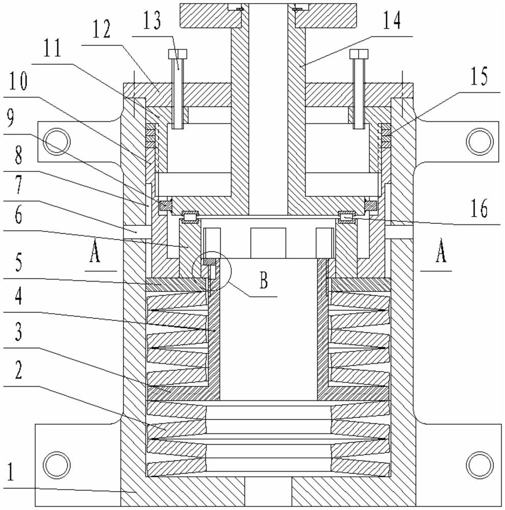
[0041] Such as figure 1 As shown, this embodiment includes a housing 1, a disc spring group and an automatic rotation mechanism. The upper end of the housing 1 is provided with an end cover 12, and the end cover 12 is connected to the housing 1 by bolts. The disc spring group is installed At the bottom inside the housing 1 , the automatic rotation mechanism is arranged between the disc spring set and the end cover 12 . The above are common structures in the prior art, and will not be repeated here.

[0042] Such as figure 1 As shown, the automatic rotation mechanism includes a guide sleeve and a rotation sleeve 14. A bar-shaped groove 8 is provided on the outside of the guide sleeve. The length direction of the bar-shaped groove 8 is consistent with the axial direction of the housing 1. The strip groove 8 is correspondingly provided with an anti-rotation bolt 7, and the en...


PUM


Abstract

The invention belongs to the field of oil pumping unit accessory equipment, and particularly relates to a sucker rod rotation anti-eccentric-wear protection device. The device comprises a shell, a disc spring set and an automatic rotation mechanism, wherein the automatic rotation mechanism comprises a guide sleeve and a rotation sleeve; a strip-shaped groove is formed in the outer side of the guide sleeve, and the length direction of the strip-shaped groove is consistent with the axis direction of the shell; an anti-rotation bolt is arranged on the side face of the shell and corresponds to thestrip-shaped groove, the tail end of the anti-rotation bolt is inserted into the strip-shaped groove so as to prevent the guide sleeve from rotating, a guide sliding way is arranged on the inner wallof the guide sleeve, and the guide sliding way is of a concave structure located on the inner wall of the guide sleeve; and the bottom of the rotation sleeve is supported on the disc spring set through a thrust bearing and a supporting structural part, a guide column is fixedly arranged on the edge of the bottom of the rotation sleeve, and the guide column extends into the guide sliding way. According to the device, the automatic rotation mechanism with the guide sliding way as the core is adopted, and quick-wear parts do not exist in the mechanism, so that the maintenance frequency is lower,and the service life is longer.

Description

technical field [0001] The invention belongs to the field of auxiliary equipment of pumping units, in particular to a protection device for preventing partial wear of sucker rod rotation. Background technique [0002] During the working process of the pumping unit, the problem of fracture and failure of the sucker rod due to eccentric wear and vibration occurs from time to time. In order to solve the problem of eccentric wear and vibration of the sucker rod, technicians have developed a variety of sucker rod protection devices. For example, a utility model patent with a document number of CN201406998Y discloses an anti-eccentric wear device for oil wells, a utility model patent with a document number of CN202788661U discloses a sucker rod energy-saving protector, and a utility model patent with a document number of CN2895705Y discloses a A multifunctional protector for sucker rods and so on. [0003] The principles of the existing sucker rod protection devices are basically...

Claims


Application Information

Patent Timeline
Patent Type & Authority Patents(China)
IPC IPC(8): E21B17/10E21B17/07
CPCE21B17/07E21B17/1064E21B17/1071
Inventor 田昊康荣富
Owner 龙沃科技开发有限公司
Why Eureka
Try Eureka