
Diaphragm and diaphragm coupling

A diaphragm coupling and diaphragm technology, applied in the direction of couplings, elastic couplings, mechanical equipment, etc., can solve the problem of affecting the operation of equipment, factory production and processing, unable to limit the amount of axial movement, diaphragm fatigue fracture, etc. problems, to achieve the effect of improving transmission stability, enhancing structural strength and improving stability

Active Publication Date: 2020-05-22
上海克兰传动设备有限公司
View PDF7 Cites 0 Cited by
  • Summary
  • Abstract
  • Description
  • Claims
  • Application Information

AI Technical Summary

Problems solved by technology

[0004] However, the structure of the diaphragm coupling in the prior art is not very reasonable, and the diaphragm coupling of the existing structure cannot limit the amount of axial movement. It is easy to cause fatigue fracture of the diaphragm, affecting the normal operation of the equipment and the normal production and processing of the factory.

Method used


Image

  • Diaphragm and diaphragm coupling
  • Diaphragm and diaphragm coupling
  • Diaphragm and diaphragm coupling

Examples


Embodiment Construction

[0033] The present invention will be described in further detail below in conjunction with the accompanying drawings.

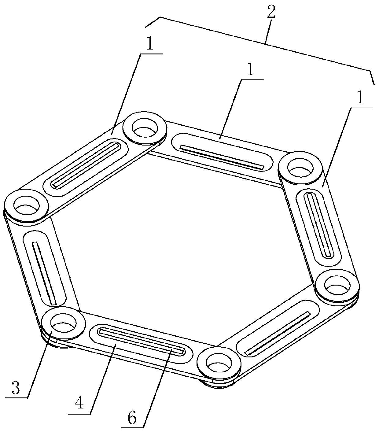
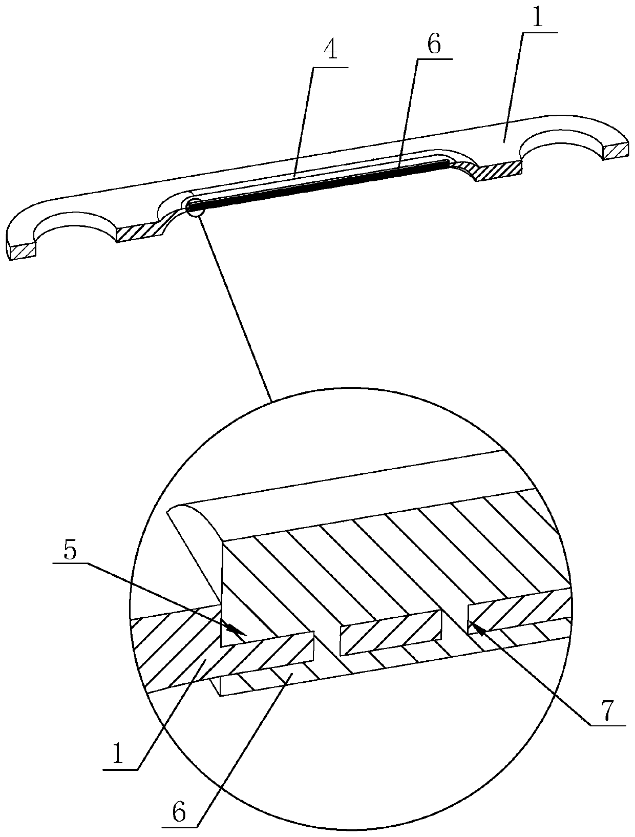
[0034] refer to figure 1 with figure 2 , is a diaphragm disclosed by the present invention, including six laminated diaphragm rods 1, and the six laminated diaphragm rods 1 are hinged end-to-end to form a diaphragm ring 2, and adjacent laminated diaphragm rods 1 are arranged alternately. A hinge ring 3 is installed at the hinge of the laminated diaphragm rod 1, and a stamping rib 4 is arranged on the laminated diaphragm rod 1 along its length direction, and the stamping rib 4 is formed by stamping on one side of the laminated diaphragm rod 1 , the raised portion of the stamped rib 4 is located between the adjacent laminated diaphragm rods 1 , and the height of the raised side of the stamped rib 4 is greater than the height of the hinge ring 3 . By stamping and processing the stamping ribs 4 on the laminated diaphragm rod 1, on the one hand, the structural ...


PUM


Abstract

The invention discloses a diaphragm and a diaphragm coupling, and relates to the field of couplings. The diaphragm comprises a plurality of laminated diaphragm rods, heads and tails between the multiple laminated diaphragm rods are hinged to form a diaphragm ring; the diaphragm is characterized in that hinged parts of the adjacent laminated diaphragm rods are provided with hinged rings; and the laminated diaphragm rods are provided with stamping bars in the length direction of the laminated diaphragm rods, and the heights of the convex sides of the stamping bars are greater than the heights ofthe hinged rings. In view of the problem that the diaphragm is fatigued and fractured due to the axial shifting force in the prior art, according to the diaphragm and the diaphragm coupling, the structural strengths of the laminated diaphragm rods are increased by arranging the stamping bars on the laminated diaphragm rods in the length direction of the laminated diaphragm rods, and the diaphragmring is not prone to being fractured due to fatigue under the condition of the periodic shifting force; and in addition, the heights of the convex sides of the stamping bars are greater than the heights of the hinged rings, and convex hulls formed by the stamping bars can also be used for buffering, the impact of axial displacement dynamic impact is reduced, and the stability of coupling transmission is improved.

Description

technical field [0001] The invention relates to the field of shaft couplings, more specifically, it relates to a membrane and a membrane coupling. Background technique [0002] Couplings are widely used in rotating machinery, including rigid couplings and elastic couplings. Diaphragm coupling is a new type of coupling, which has the advantages of transmitting large torque, allowing large displacement error, generally does not need lubrication, and is easy to install and maintain. It is widely used in national defense, shipbuilding, aviation, petrochemical industry , vehicles, machinery and other industries, can replace the coupling devices such as gear couplings, elastic sleeve pin couplings and so on. [0003] For the existing diaphragm coupling structure, such as the Chinese patent with the patent publication number CN201016368, it discloses a diaphragm coupling, which includes two half-couplings arranged oppositely, and the two half-coupling parts A diaphragm is connect...

Claims


Application Information

Patent Timeline
IPC IPC(8): F16D3/56F16D3/58
CPCF16D3/56F16D3/58
Inventor 陈泽华
Owner 上海克兰传动设备有限公司
Learn More