Auxiliary teaching device
A technology for assisting teaching and display boards, applied in the field of teaching, can solve problems such as inconvenient operation, and achieve the effect of simple structure and low cost
- Summary
- Abstract
- Description
- Claims
- Application Information
AI Technical Summary
Problems solved by technology
Method used
Image


Examples
Embodiment 1
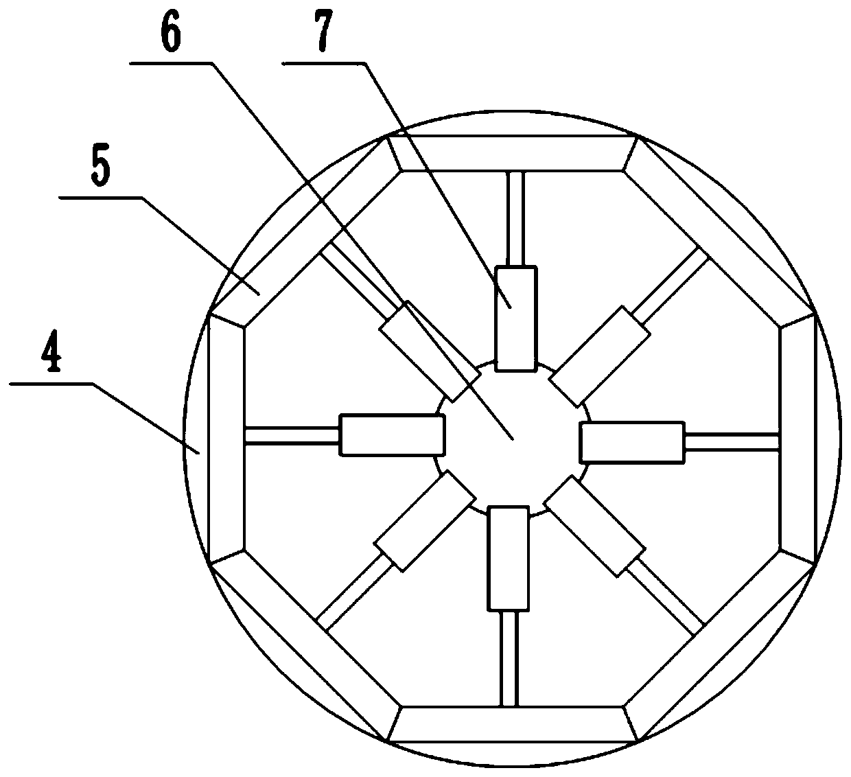
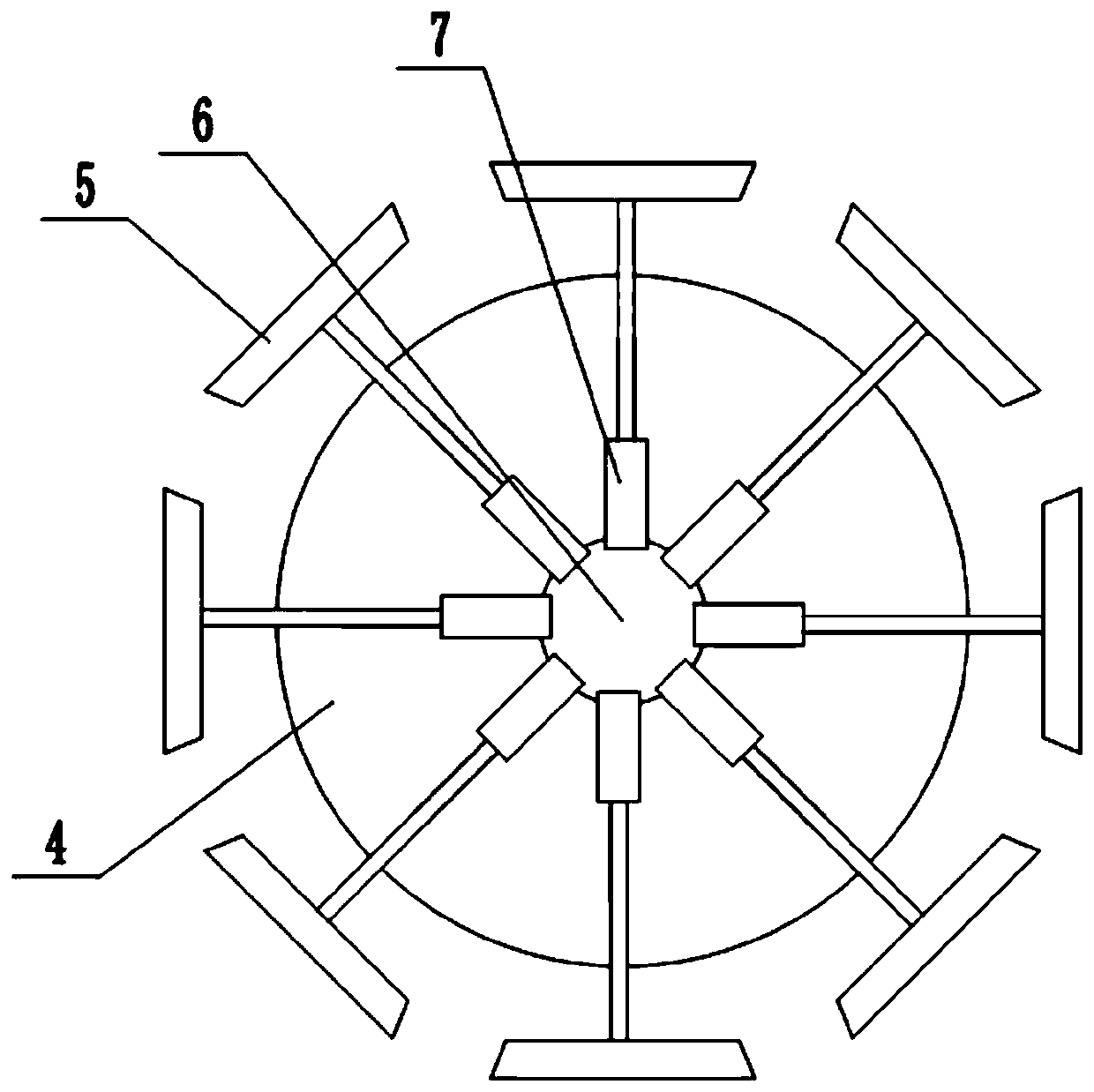
[0029] Basic as attached Figure 1-Figure 4 As shown: an auxiliary teaching device, including a circular base 1, four support plates are welded on the bottom of the base 1, and wheels 2 are connected to the support plates through pin shaft rotation. The upper surface of the base 1 is rotatably connected with a turntable 4. Specifically, the upper surface of the base 1 is provided with an annular groove, and the bottom of the turntable 4 is welded with an annular bar, and the annular bar is located in the annular groove. The turntable 4 is provided with a display mechanism, combined with figure 2 As shown, the display mechanism in this embodiment includes eight vertically arranged display boards 5 and a telescopic assembly for controlling the lateral movement of the display boards 5, figure 2 The cross-sectional shape formed by the eight display boards 5 is a regular octagon. A vertical shaft 6 is coaxially welded on the turntable 4, and the axis of the vertical shaft 6 pas...
Embodiment 2
[0033] combine Figure 5 As shown, the difference between this embodiment and Embodiment 1 is that the structure of the telescopic assembly is different, the telescopic assembly includes two moving blocks 9 and sixteen connecting rods 10, and the vertical shaft 6 in this embodiment is a two-way lead screw , the two moving blocks 9 are respectively threaded on the two ends of the two-way lead screw, and the two ends of the connecting rod 10 are hinged on the moving block 9 and the display board 5 . The ends of the two connecting rods 10 on the same display board 5 are located on the display board 5 and are close to each other, and the ends on the moving block 9 are far away from each other; two guide rods 12 are welded on the turntable 4, combined with Figure 6 As shown, the two guide rods 12 are arranged symmetrically with respect to the vertical axis 6 . The moving block 9 is provided with a hole through which the guide rod 12 passes, thereby realizing the vertical sliding ...
Embodiment 3
[0036] combine Figure 7 As shown, teaching cards can be placed on the display board 5 in this embodiment, and the display board 5 is made of transparent plastic. The inside of the display board 5 is provided with a card chamber, and the top of the display board 5 is provided with a socket communicating with the card chamber, Figure 7 The right side wall of the middle display board 5 is provided with a vertical sliding groove 13 communicating with the card cavity, and the interior of the card cavity is vertically slidably connected with an "L"-shaped push part 14, specifically, the horizontal side of the push part 14 Located in the card cavity, a vertical groove is arranged on the left inner wall of the card cavity, the left end of the horizontal side of the pushing part 14 is positioned in the vertical groove, and the vertical side of the pushing part 14 is positioned in the sliding groove 13 . The vertical edge of the push part 14 is bonded with anti-slip stripes on the ou...
PUM
 Abstract
Description
Claims
Application Information
 - R&D
- Intellectual Property
- Life Sciences
- Materials
- Tech Scout
- Unparalleled Data Quality
- Higher Quality Content
- 60% Fewer Hallucinations
Browse by: Latest US Patents, China's latest patents, Technical Efficacy Thesaurus, Application Domain, Technology Topic, Popular Technical Reports.
© 2025 PatSnap. All rights reserved.Legal|Privacy policy|Modern Slavery Act Transparency Statement|Sitemap|About US| Contact US: help@patsnap.com