Battery transferring frame

A transfer rack and battery technology, applied in transportation and packaging, containers, packaging, etc., can solve the problems of time-consuming and labor-intensive, easy to damage batteries, etc., and achieve the effects of avoiding scratches, simplifying the structure, and simple structure

Inactive Publication Date: 2020-05-26
STATE GRID TIANJIN ELECTRIC POWER +3
View PDF10 Cites 4 Cited by
  • Summary
  • Abstract
  • Description
  • Claims
  • Application Information

AI Technical Summary

Problems solved by technology

[0004] The purpose of the present invention is to provide a battery transfer rack, which can solve the problem that the process of placing the battery on the transfer rack when the operator uses the transfer rack in the prior art is time-consuming and laborious, and the battery is easy to be damaged

Method used


Image

  • Battery transferring frame
  • Battery transferring frame
  • Battery transferring frame

Examples


Embodiment 1

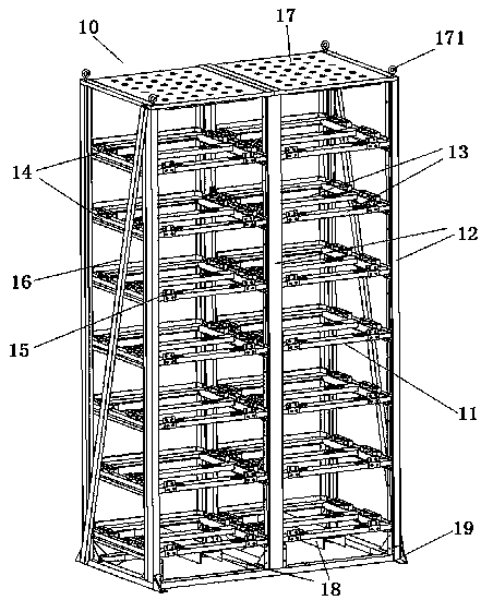
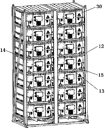
[0046] Embodiment 1 of the battery transfer rack in the present invention: the battery transfer rack in the present invention can carry battery sub-boxes, and the operator can carry out long-distance or short-distance transfer of multiple battery sub-boxes by moving the battery transfer rack. Such as figure 1 and figure 2 As shown, the battery transfer frame 10 includes a carrier frame 11 as a main body. The carrier frame 11 in this embodiment includes six columns 12 extending vertically, and the lines connecting the six columns 12 form a rectangle. The bearing frame 11 also includes supporting brackets that are connected to the uprights 12 at intervals along the up-down direction, that is, multi-layer supporting brackets are arranged in the up-down direction, and in the up-down direction, two adjacent supporting brackets are formed for The battery storage compartment supporting the battery insertion box 30 has an opening for the battery to enter and exit the battery storage...

Embodiment 2

[0060] Embodiment 2 of the battery transfer rack in the present invention: the difference from the above embodiment is that the carrier rack in this embodiment is provided with an independent box body, the battery storage compartment is formed by the box body, and the battery is loaded into the corresponding box during transfer. In the box body, a bottom support structure is arranged on the bottom wall of the box body, and a side guide structure is arranged on the side wall.

Embodiment 3

[0061] Embodiment 3 of the battery transfer frame in the present invention: the difference from the above embodiments is that the carrier frame in this embodiment includes a column and a plate body connected to the column, and the plate body includes side plates arranged in a vertical direction. As well as the top plate and the bottom plate arranged in the horizontal direction, the battery storage compartment is jointly surrounded by the side plates, the top plate and the bottom plate. Bottom support structures are arranged on the base plate and side guide structures are arranged on the side plates.

[0062] Embodiment 4 of the battery transfer rack in the present invention: the difference from the above embodiments is that the bottom supporting structure in this embodiment is only arranged on the longitudinal beams. In other embodiments, bottom support structures are provided on both the longitudinal beams and the cross beams.


PUM


Abstract

The invention relates to a battery transferring frame to solve the problems in the prior art that both time and labor are wasted and the battery is likely to be damaged when the battery is placed on the transferring frame. The battery transferring frame comprises a bearing frame, battery placing cabins, a bottom support mechanism, lateral guiding structures and limiting pieces, wherein at least one row of battery placing cabins are arranged on the bearing frame in the up-down direction; each of the battery placing cabins is provided with a cabin opening allowing the battery to enter and exit the battery placing cabin, and the cabin opening is towards the horizontal direction; the bottom support mechanism is mounted at the bottoms of the battery placing cabins and comprises a ball or an idler wheel; the ball or the idler wheel is used for being in rolling contact with the bottom of the battery; the lateral guiding structures are mounted on the two sides of the battery placing cabins; each of the lateral guiding structures comprises balls or idler wheels distributed in the depth direction of the battery placing cabins; the balls or idler wheels are used for being in rolling contact with the side walls of the batteries and directing the batteries to enter the battery placing cabins; and the limiting pieces are detachably or movably mounted at all battery placing cabins and are used for being in stop fit with the batteries in the directions entering and/or exiting the battery placing cabins.

Description

technical field [0001] The invention relates to a battery transfer frame. Background technique [0002] With the development of technology, the performance of lithium-ion batteries has gradually improved, and they are widely used in electric energy storage and new energy automobile industries. Due to the small capacity and voltage level of lithium-ion single batteries, technicians will connect multiple single batteries in series and parallel to form a battery module with a certain capacity and voltage level for use. [0003] The number of single cells required for battery module assembly is large, and the operator needs to transport the battery modules or single cells required for assembly to the assembly site. In the prior art, there are two ways of transporting battery modules or single cells. One way is to pack each battery module or single battery individually with a protective layer, and then transport the single cells or battery modules, relying on wrapping in a singl...

Claims


Application Information

Patent Timeline
Patent Type & Authority Applications(China)
IPC IPC(8): B65D88/12B65D90/00
CPCB65D88/12B65D90/00B65D90/0073
Inventor 司威张志朋刘慧芳周亚楠张金禄张建海于天一李鹏程闫龙田刚领罗军董蕊何玉龙乐坤李春晖李海龙徐奕翔李贺阮鹏
Owner STATE GRID TIANJIN ELECTRIC POWER
Why Eureka
Try Eureka