Pressurizing cylinder and clamp device applying same

A technology of pressurizing cylinder and cylinder block, which is applied to fluid pressure actuating devices, chucks, manufacturing tools, etc., can solve the problems of small thrust, inability to clamp workpieces, and unstable cylinder output thrust.

Pending Publication Date: 2020-05-26
希格斯精密机械(苏州)有限公司
View PDF0 Cites 0 Cited by
  • Summary
  • Abstract
  • Description
  • Claims
  • Application Information

AI Technical Summary

Problems solved by technology

However, the compressed air used by the cylinder has a certain degree of compressibility, and the pressure of the compressed air is generally below 6bar, which causes the output thrust of the cylinder to be unstable and the thrust is too small, which in turn makes the clamping force of the clamping device

Method used


Image

  • Pressurizing cylinder and clamp device applying same
  • Pressurizing cylinder and clamp device applying same
  • Pressurizing cylinder and clamp device applying same

Examples


Embodiment 1

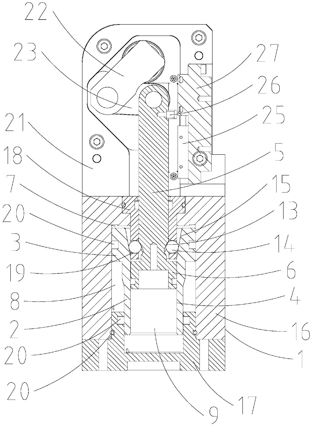
[0044] Such as Figure 1~5 Shown, a kind of pressurized cylinder, it comprises cylinder body 1, first piston part and second piston part; Wherein,

[0045] An inner cavity is provided in the cylinder body 1;

[0046] The first piston part is arranged in the inner cavity, and the first piston part includes a first rod part 2, a first piston part 3 connected to the upper end part of the first rod part 2, and a first piston part 3 passing through the first rod part 2. A rod part 2 and a piston hole 4 of the first piston part 3, the lower end part of the first rod part 2 and the first piston part 3 are both sealed and slidingly connected with the cylinder body 1;

[0047]The second piston part includes a second rod part 5 and a second piston part 6, the second piston part 6 is connected in the piston hole 4 in a sealing and sliding fit, and the lower end of the second rod part 5 is connected to the On the second piston part 6, the upper end of the second rod part 5 protrudes out...

Embodiment 2

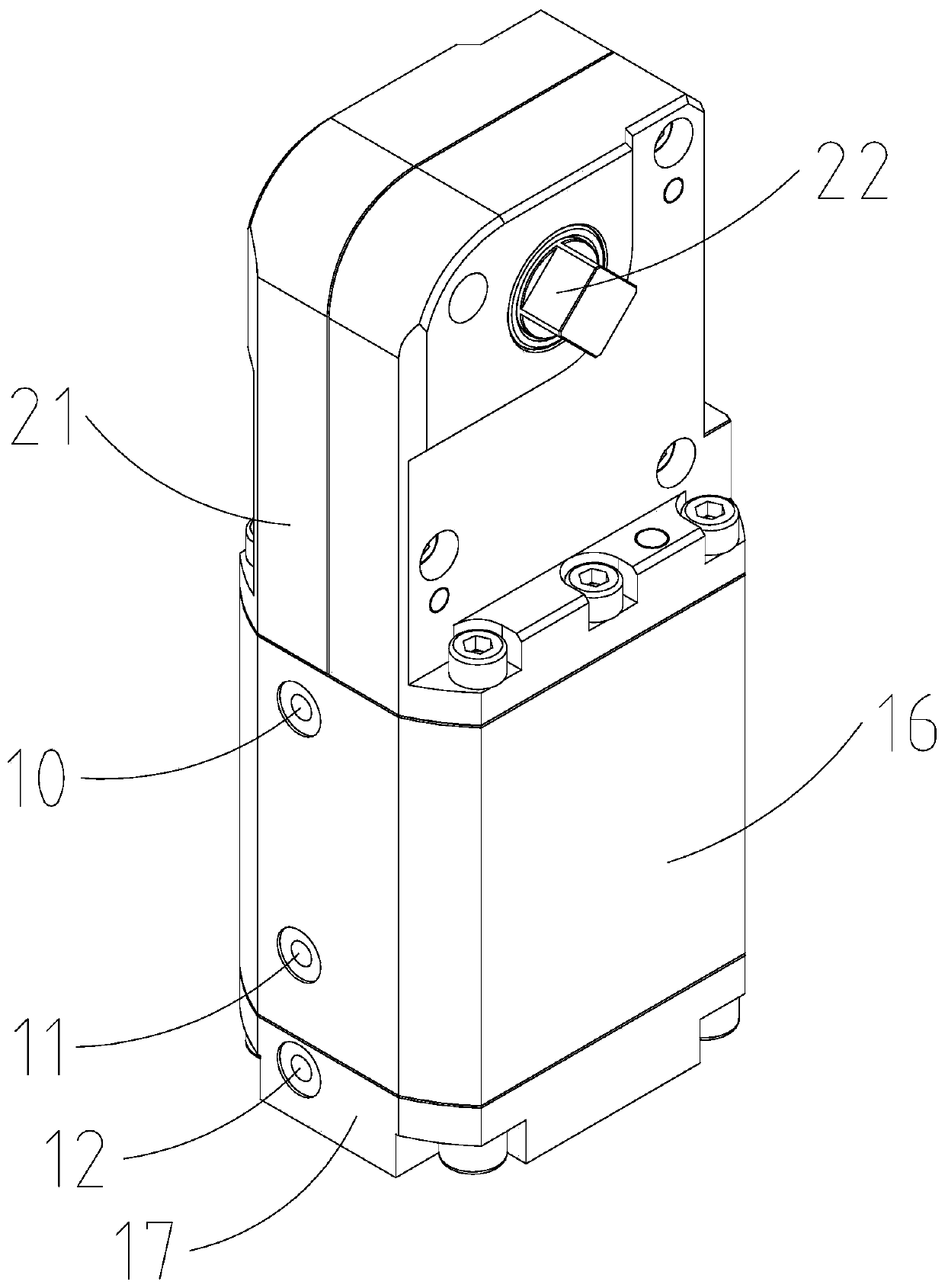
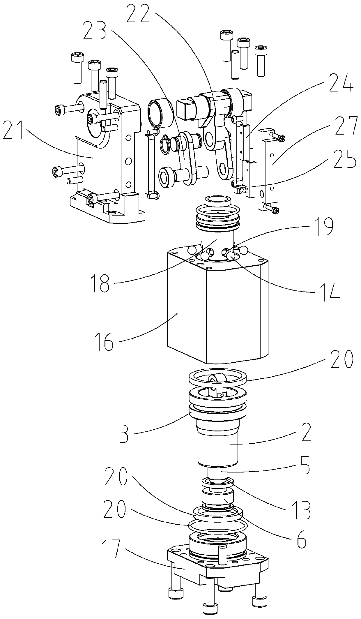
[0066] Such as Figure 1~3 As shown, a clamp device includes the pressurized cylinder described in Embodiment 1, and it also includes a housing 21, a transmission mechanism and a clamping part; wherein,

[0067] The housing 21 is connected to the cylinder 1 or integrated with the cylinder 1;

[0068] The transmission mechanism is connected to the housing 21 and connected to the upper end of the second rod 5;

[0069] The clamping part is connected to the transmission mechanism, so that when the second rod part 5 is driven to move, the second rod part 5 drives the clamping part to act through the transmission mechanism to clamp the external The workpiece; in this embodiment, the housing 21 is connected to the upper end of the cylinder 16 by bolts.

[0070] Such as Figure 1~3 As shown, the transmission mechanism is for example but not limited to the following structure, which includes a crank 22 and a connecting rod 23; wherein,

[0071] The clamping part is connected to th...


PUM


Abstract

The invention discloses a pressure cylinder. The pressure cylinder comprises a cylinder body, a first piston component and a second piston component; the first piston component comprises a first rod part, a first piston part and a piston hole, and the lower end part of the first rod part and the first piston part are connected with the cylinder body in a sealing and sliding fit manner; the secondpiston component comprises a second rod part and a second piston part, the second piston part is connected into the piston hole in a sealing and sliding fit mode, and the second rod part is connectedwith the cylinder body in a sealing and sliding fit mode; and a pressurizing conical surface is arranged at the lower end of the second rod part, a pressurizing ball is embedded in the cylinder body,and a pressure conical surface is arranged at the upper end of the piston hole, so that the pressure conical surface abuts against the pressurizing ball and drives the pressurizing ball to move towards the second rod part, and then the second piston part is driven to move upwards. According to the pressure cylinder, the output thrust can be greatly improved, then the clamping force for clamping aworkpiece is improved, the structure is compact, the size is small, and the space can be saved.

Description

technical field [0001] The invention relates to a booster cylinder and a clamp device using the same. Background technique [0002] At present, industrial robots usually need to use fixtures to grab and carry workpieces in practical applications. Due to the limited space in industrial robots, compact pneumatic fixtures are widely used. The principle is to output thrust through the cylinders in the fixtures. To realize the clamping of the workpiece. However, the compressed air used by the cylinder has a certain degree of compressibility, and the pressure of the compressed air is generally below 6bar, which causes the output thrust of the cylinder to be unstable and the thrust is too small, which in turn makes the clamping force of the clamping device too small to be For clamping workpieces with heavy loads. In order to obtain a larger clamping force, some designers use double-force cylinders, but this leads to a larger volume of the fixture device, which takes up more space...

Claims


Application Information

Patent Timeline
IPC IPC(8): F15B3/00F15B15/14B25J15/00
CPCB25J15/00F15B3/00F15B15/1423F15B15/1428F15B15/1442F15B15/1447F15B15/1461
Inventor 何岚岚徐庆富
Owner 希格斯精密机械(苏州)有限公司
Why Eureka
Try Eureka