Self-operated nitrogen seal valve

A self-operated, nitrogen-sealed technology, applied in lift valve, shaft seal, valve details, etc., can solve the problems of affecting the use effect, not compact, and large volume of the membrane head.

Pending Publication Date: 2020-07-07
浙江中孚流体机械有限公司
View PDF0 Cites 0 Cited by
  • Summary
  • Abstract
  • Description
  • Claims
  • Application Information

AI Technical Summary

Problems solved by technology

At present, the film head of nitrogen sealing device products on the market is placed horizontally, without force arm structure, and the film head directly interacts with the valve stem. The film head is bulky and not compact, which affects the use effect.

Method used


Image

  • Self-operated nitrogen seal valve
  • Self-operated nitrogen seal valve
  • Self-operated nitrogen seal valve

Examples


Embodiment 1

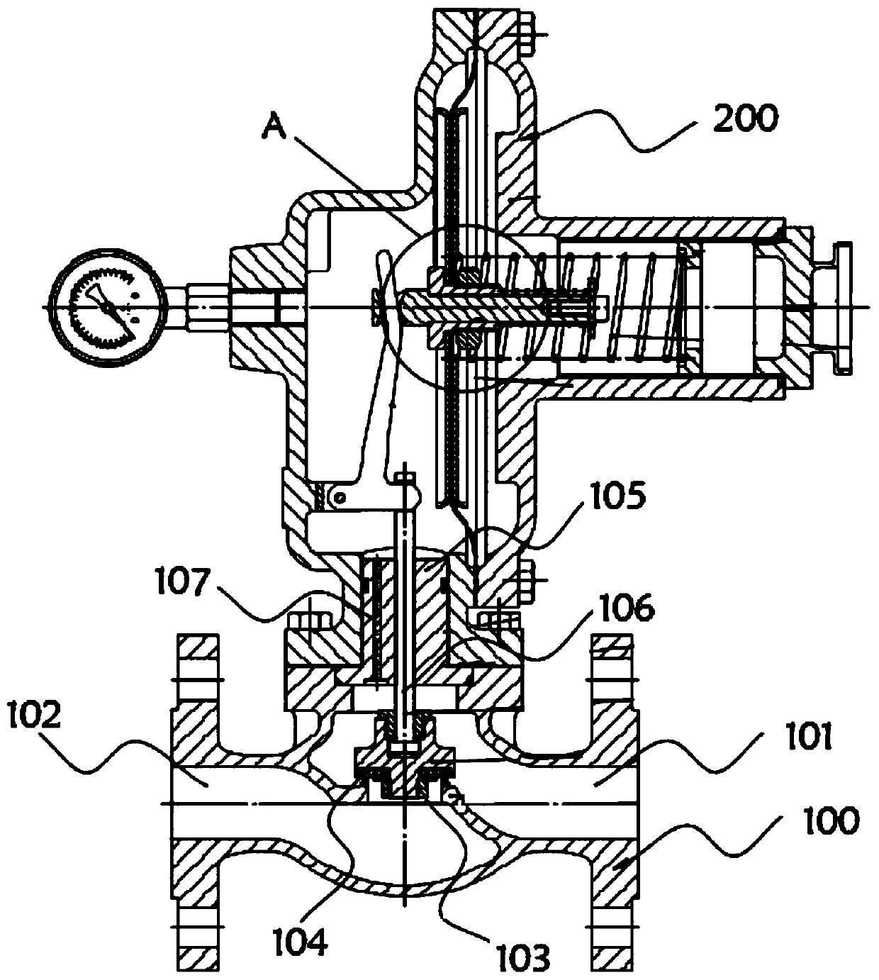
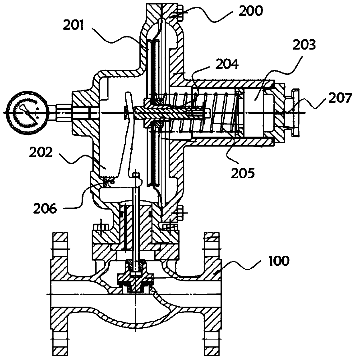
[0032] see Figure 1-Figure 6 As shown, the present invention provides a self-operated nitrogen sealing valve, which includes a valve body 100 and a pneumatic actuator 200 installed on the top of the valve body 100. A diaphragm 201 is installed inside the pneumatic actuator 200, and the diaphragm 201 is made of elastic material. As a result, preferably, the diaphragm 201 is made of rubber material, which has good toughness and can shrink. At the same time, the rubber material is well sealed and can block gas. The diaphragm 201 is vertically installed inside the pneumatic actuator 200 to save pneumatic execution. The occupied area of ​​the internal space of the actuator 200, the diaphragm 201 divides the interior of the pneumatic actuator 200 into a transmission chamber 202 and an exhaust chamber 203, the transmission chamber 202 is used to control the internal gas passage of the valve body 100, and the central position of the diaphragm 201 is installed Ferrule 208 , a push rod...


PUM


Abstract

The invention relates to the technical field of valves, and particularly relates to a self-operated nitrogen seal valve. The self-operated nitrogen seal valve comprises a valve body and a pneumatic actuator mounted at the top of the valve body, wherein a diaphragm is mounted in the pneumatic actuator and divides the interior of the pneumatic actuator into a transmission cavity and an exhaust cavity; a clamping sleeve is mounted in the center of the diaphragm; a push rod is mounted in the clamping sleeve; and a driving rod is mounted at one end of the push rod. Through the structural design ofthe self-operated nitrogen seal valve, self-operated adjustment of the valve body is achieved, the diaphragm does not occupy the internal space area of the pneumatic actuator, the space utilization rate is increased, meanwhile, the output thrust of the driving rod is large, a valve rod is controlled to move conveniently, and the transmission working efficiency is improved.

Description

technical field [0001] The invention relates to the technical field of valves, in particular to a self-operated nitrogen sealing valve. Background technique [0002] The nitrogen blanketing device is mainly used on the top of the storage tank to maintain the slight positive pressure of the storage tank, isolate the contact between the material and the outside world, reduce the volatilization and waste of the material, and protect the safety of the storage tank. At present, the film head of nitrogen sealing device products on the market is placed horizontally, without force arm structure, and the film head directly interacts with the valve stem. The film head is bulky and not compact, which affects the use effect. Contents of the invention [0003] The object of the present invention is to provide a self-operated nitrogen sealing valve to solve the problems raised in the above-mentioned background technology. [0004] In order to achieve the above object, the present inven...

Claims


Application Information

Patent Timeline
IPC IPC(8): F16K1/36F16K41/02F16K37/00F16K31/385F16K27/02F16K31/44F16K31/126
CPCF16K1/36F16K27/02F16K31/1262F16K31/1266F16K31/385F16K31/44F16K37/00F16K41/02
Inventor 谢海勇谢海龙徐华丰金春
Owner 浙江中孚流体机械有限公司
Why Eureka
Try Eureka