
Wind turbine generator blade tip lightning protection loop resistance testing device

A technology of testing device and loop resistance, applied in the direction of measuring device, measuring device casing, measuring resistance/reactance/impedance, etc. Problems such as difficult wiring, to achieve the effect of solving incomplete testing, good social and economic benefits, and reducing the risk of lightning accidents

Pending Publication Date: 2020-05-26
CENT CHINA BRANCH OF CHINA DATANG CORP SCI & TECH RES INST CO LTD
View PDF0 Cites 3 Cited by
  • Summary
  • Abstract
  • Description
  • Claims
  • Application Information

AI Technical Summary

Problems solved by technology

Since the wind turbine blade air-termination device is arranged at the tip of the blade, it is difficult to connect the air-termination device at the blade tip during the circuit resistance test process, and there is a great potential safety hazard in putting the maintenance personnel to the blade tip for wiring through the safety rope
Therefore, in the actual test, the lightning protection part of the blade is basically ignored, resulting in the incompleteness of the loop resistance test
At the same time, due to the broken strands of the lightning protection down conductor of the blade or the contact breakage between the lightning protection down conductor and the lightning receptor, the wind turbine suffered from lightning strikes many times. Therefore, the inspection and maintenance of the lightning protection system of the wind turbine should be strengthened to solve the incomplete lightning protection circuit resistance test. The problem is imminent

Method used


Image

  • Wind turbine generator blade tip lightning protection loop resistance testing device
  • Wind turbine generator blade tip lightning protection loop resistance testing device
  • Wind turbine generator blade tip lightning protection loop resistance testing device

Examples


Embodiment Construction

[0020] The specific implementation manners of the present invention will be described in further detail below in conjunction with the accompanying drawings.

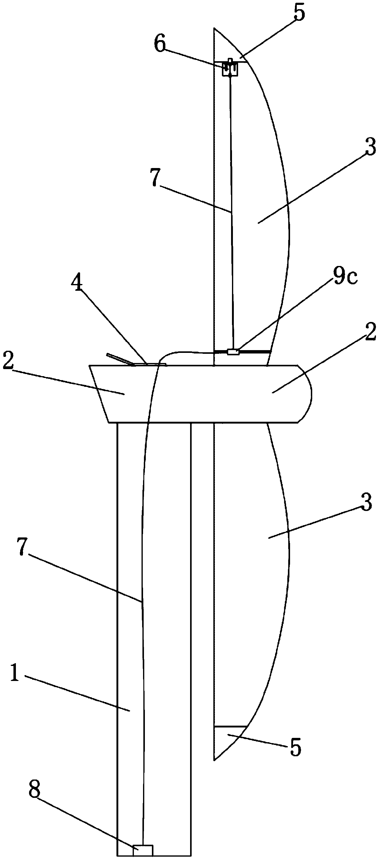
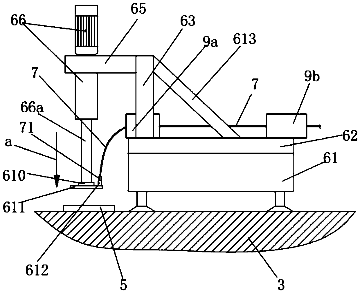
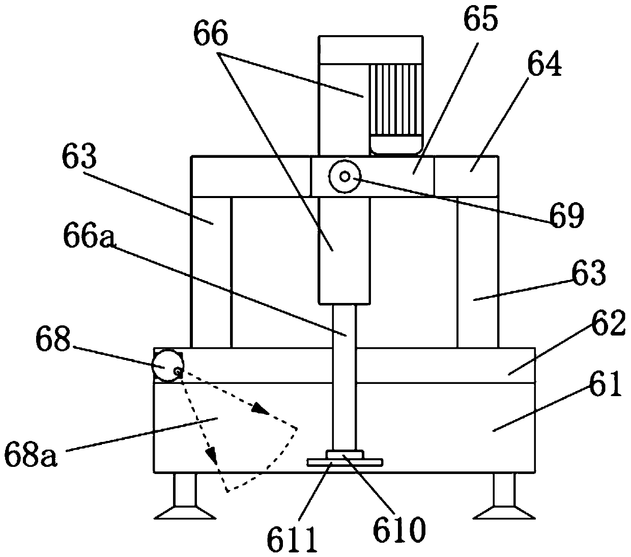
[0021] Depend on Figure 1-8 Given, the present invention comprises a tower 1, a nacelle 2 rotatably arranged at the upper end of the tower, and a plurality of blades 3 rotatably arranged at the front end of the nacelle 2, and the tip portion (outer end / tip) of the blade 3 is equipped with a lightning receptor device 5, the wind turbine blade tip lightning protection circuit resistance testing device also includes a crawling device 6, a testing device 8 and a test wire 7, the crawling device includes a crawling mechanism 61 crawling along the surface of the blade, and a bottom plate 62 is fixed on the top of the crawling mechanism 61, and the bottom plate The upper part of the front end of 62 is fixedly connected with a support frame protruding upwards, and the upper end of the support frame is fixedly connected with a p...


PUM


Abstract

The invention relates to a wind turbine generator blade tip lightning protection loop resistance testing device. The technical scheme is as follows: a crawling device comprises a crawling mechanism crawling along the surfaces of the blades; a bottom plate is fixed above the crawling mechanism; the upper part of the front end of the bottom plate is fixedly connected with a supporting frame; the upper end of the supporting frame is fixedly connected with a push rod motor fixing frame; a push rod motor is fixed on the push rod motor fixing frame; a wiring terminal is fixed at the lower end of a telescopic rod of the push rod motor; a first camera and a second camera are respectively arranged on the crawling device; one end of the test wire is connected with the wiring terminal; and the otherend of the test wire is connected with the test device. Through the crawling device, crawling and moving on the surface of the blade can be remotely controlled; through the push rod motor, the quick connection of the wiring terminal and the lightning arrester is completed; and the test wire is guided through the test wire guide box, so that the potential safety hazard that maintainers perform high-altitude wiring operation at the blade tip is avoided.

Description

technical field [0001] The invention relates to a resistance testing device for a blade tip lightning protection circuit of a wind turbine. Background technique [0002] As we all know, due to the existence of wind shear, the higher the altitude, the better the resources. Therefore, many wind farms are located in mountainous areas with higher altitudes. In addition, the capacity of wind turbines is increasing, and their towers and blades are also increasing. Therefore, the lightning protection of wind turbines has become an important link in the safe operation of wind turbines. "Technical Specifications for Lightning Protection System for Wind Turbine Generating Sets" (NB / T31039-2012), "Lightning Protection for Wind Turbine Generating Sets" (GBZ 25427-2010) and other countries and energy industries have made specific regulations on lightning protection for wind turbines. Generally, the lightning protection system of wind turbines mainly consists of blade lightning protectio...

Claims


Application Information

Patent Timeline
Patent Type & Authority Applications(China)
IPC IPC(8): G01R27/02G01R1/04
CPCG01R27/02G01R1/0416
Inventor 蔡高原魏庆海李彬王洒赵琼婧
Owner CENT CHINA BRANCH OF CHINA DATANG CORP SCI & TECH RES INST CO LTD
Learn More