Unlock instant, AI-driven research and patent intelligence for your innovation.

Flyback converter control method and flyback converter control circuit

A technology of flyback converter and control method, which is applied in control/regulation system, conversion of DC power input to DC power output, instruments, etc., which can solve the problems that cannot be adjusted accurately in real time, and achieve both power density and optimized conversion efficiency effect

Active Publication Date: 2020-05-26
SOUTHCHIP SEMICON TECH SHANGHAI CO LTD
View PDF7 Cites 4 Cited by
  • Summary
  • Abstract
  • Description
  • Claims
  • Application Information

AI Technical Summary

Problems solved by technology

However, due to the influence of cable voltage compensation, slope compensation and other factors, the relationship between the feedback signal FB and the load is not linear. Using the feedback signal FB as the frequency reduction condition has limitations, and it cannot be adjusted accurately in real time.

Method used


Image

  • Flyback converter control method and flyback converter control circuit
  • Flyback converter control method and flyback converter control circuit
  • Flyback converter control method and flyback converter control circuit

Examples


Embodiment 1

[0050] Embodiment 1. Adjusting the switching frequency according to the output current

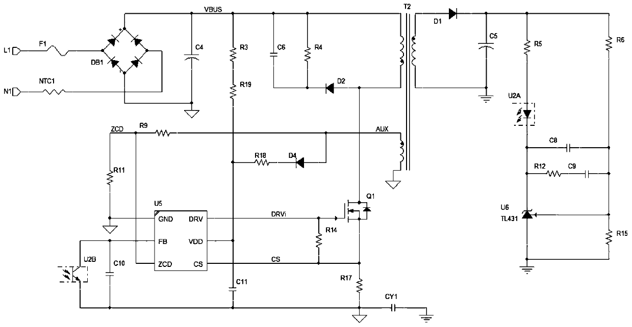
[0051] Embodiment 1 provides an implementation scheme for obtaining the control signal CCsg proportional to the secondary current information of the flyback converter by monitoring the voltage on the primary side current detection resistor R17 combined with the freewheeling feedback of the auxiliary winding, including the following steps:

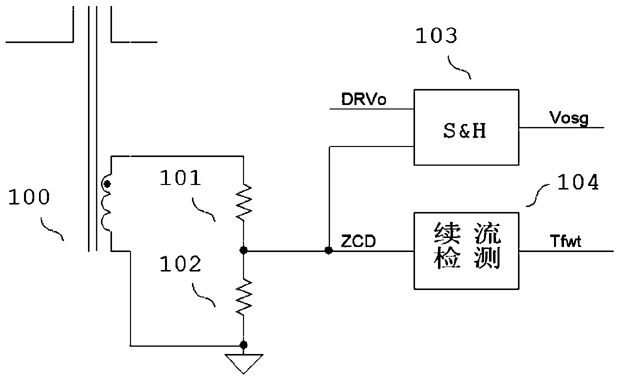
[0052] 1.1. When the gate drive signal DRVi of the switch tube Q1 controls the switch tube Q1 to turn off, sample and hold the voltage signal CS on the primary side current detection resistor R17, and obtain the peak voltage signal of the voltage signal CS on the primary side current detection resistor CSpk.

[0053] 1.2. After the gate drive signal DRVi of the switch tube Q1 effectively controls the switch tube Q1 to turn on, sample and hold the voltage signal CS on the primary side current detection resistor R17 to obtain the valley of the voltage sig...

Embodiment 2

[0064] Embodiment 2. Adjusting the switching frequency according to the output power

[0065] In the first embodiment, the control signal CCsg represents the secondary current information, and the frequency control is performed by using the secondary current information. Embodiment 2 In Embodiment 1, on the basis of monitoring the voltage on the primary side current detection resistor R17 combined with the freewheeling feedback of the auxiliary winding, the feedback Vosg of the secondary voltage is introduced to obtain a value proportional to the secondary power information of the flyback converter. The control signal CCsg provides a scheme to control the switching frequency by using the control signal CCsg which is proportional to the secondary power information of the flyback converter. The detailed method is: after summing the peak voltage signal CSpk and the valley voltage signal CSvl of the voltage signal CS on the primary side current detection resistor in step 1.3 of th...


PUM


Abstract

The invention discloses a flyback converter control method and a flyback converter control circuit, and belongs to the technical field of switching power supplies. The method comprises the steps thatfirstly, a control signal in direct proportion to secondary current information or secondary power information of a flyback converter is extracted, then the switching frequency of the flyback converter is adjusted according to the control signal, and the larger the control signal is, the higher the switching frequency of the flyback converter is. The invention provides a method for obtaining secondary current information by monitoring voltage on a primary side current detection resistor and combining follow current feedback of an auxiliary winding. In addition, secondary power information canbe obtained by introducing secondary voltage feedback on the basis. Different from a traditional control scheme in which adjustment is limited due to the fact that the feedback signal of output voltage of the flyback converter is used as a basis, the method takes the secondary current information or the secondary power information of the flyback converter as a basis to adjust the switching frequency of the flyback converter, and the switching frequency can be accurately adjusted in real time according to the load condition.

Description

technical field [0001] The invention belongs to the technical field of switching power supplies, and relates to a control method of a flyback converter and a control circuit of a flyback converter capable of realizing the control method. Background technique [0002] Flyback converter, also known as single-ended flyback or "Buck-Boost" converter, gets its name because the output terminal obtains energy when the primary winding is disconnected from the power supply. Because of its simple circuit structure and low cost, the flyback converter is widely used in low-power power supplies and various power adapters. [0003] There are many control methods for the energy transmission of the flyback converter. For example, the commonly used closed-loop control is realized by the secondary through the optocoupler to adjust the voltage of the feedback signal FB of the output voltage of the flyback converter, that is, the voltage of FB determines the energy transfer. In addition, it al...

Claims


Application Information

Patent Timeline
IPC IPC(8): H02M3/335
CPCH02M3/33523
Inventor 高建龙杨坤陶权保
Owner SOUTHCHIP SEMICON TECH SHANGHAI CO LTD
Features
  • R&D
  • Intellectual Property
  • Life Sciences
  • Materials
  • Tech Scout
  • Unparalleled Data Quality
  • Higher Quality Content
  • 60% Fewer Hallucinations
Learn More