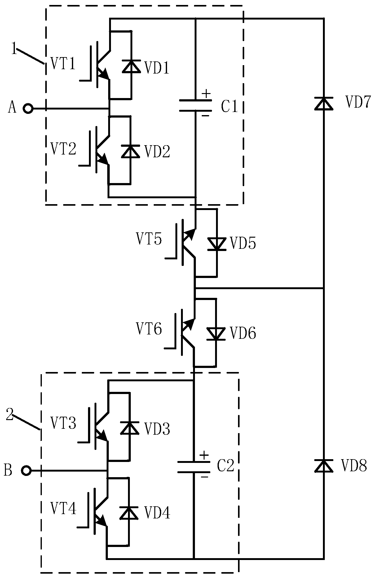
MMC sub-module topological structure with DC fault blocking capability equivalent to that of full-bridge sub-module
A full-bridge sub-module and DC fault technology, applied in the direction of converting AC power input to DC power output, power transmission AC network, output power conversion device, etc., can solve the problems of increased equipment cost, high cost, and large number of transistors , to achieve the effect of suppressing fault current and reducing economic cost
- Summary
- Abstract
- Description
- Claims
- Application Information
AI Technical Summary
Problems solved by technology
Method used
Image

Examples
Embodiment 1
[0053] Build a flexible DC transmission system simulation model in MATLAB / Simulink, such as Figure 5 As shown, the MMC converter station topology is as follows Figure 6 As shown, each bridge arm contains sub-modules n=6, the sub-modules adopt the topology proposed by the present invention, and the parameters of the flexible straight system simulation model are shown in Table 2 below.
[0054] Table 2
[0055]
[0056] When the system is working normally, the active and reactive power waveforms transmitted by the system are as follows: Figure 7 As shown, the DC side current is as Figure 8 As shown, the bridge arm voltage is as Figure 9 As shown, the sub-module current is as Figure 10 shown. It can be seen that the system runs smoothly, the fluctuation of active power and reactive power is small, the fluctuation of DC side current is small, the voltage of the bridge arm is close to sinusoidal, and the sinusoidal and symmetry of the sub-module current is good, indic...
PUM
 Abstract
Description
Claims
Application Information
 - R&D
- Intellectual Property
- Life Sciences
- Materials
- Tech Scout
- Unparalleled Data Quality
- Higher Quality Content
- 60% Fewer Hallucinations
Browse by: Latest US Patents, China's latest patents, Technical Efficacy Thesaurus, Application Domain, Technology Topic, Popular Technical Reports.
© 2025 PatSnap. All rights reserved.Legal|Privacy policy|Modern Slavery Act Transparency Statement|Sitemap|About US| Contact US: help@patsnap.com