
Rotating electrical machine provided with a wedging element

A technology for rotating motors and components, applied in electrical components, electromechanical devices, electric components, etc., can solve problems such as insufficient sensor contact, and achieve the effect of improving heat exchange and reducing response time

Active Publication Date: 2020-05-26
VALEO EQUIP ELECTRIC MOTEUR
View PDF3 Cites 0 Cited by
  • Summary
  • Abstract
  • Description
  • Claims
  • Application Information

AI Technical Summary

Problems solved by technology

However, since the shape of the elastic support is insufficient to correspond to the bun 23, the contact between the sensor 4 and the bun 23 is still insufficient.

Method used


Image

  • Rotating electrical machine provided with a wedging element
  • Rotating electrical machine provided with a wedging element
  • Rotating electrical machine provided with a wedging element

Examples


Embodiment Construction

[0043] Unless otherwise stated, identical elements shown in different figures have a single reference sign.

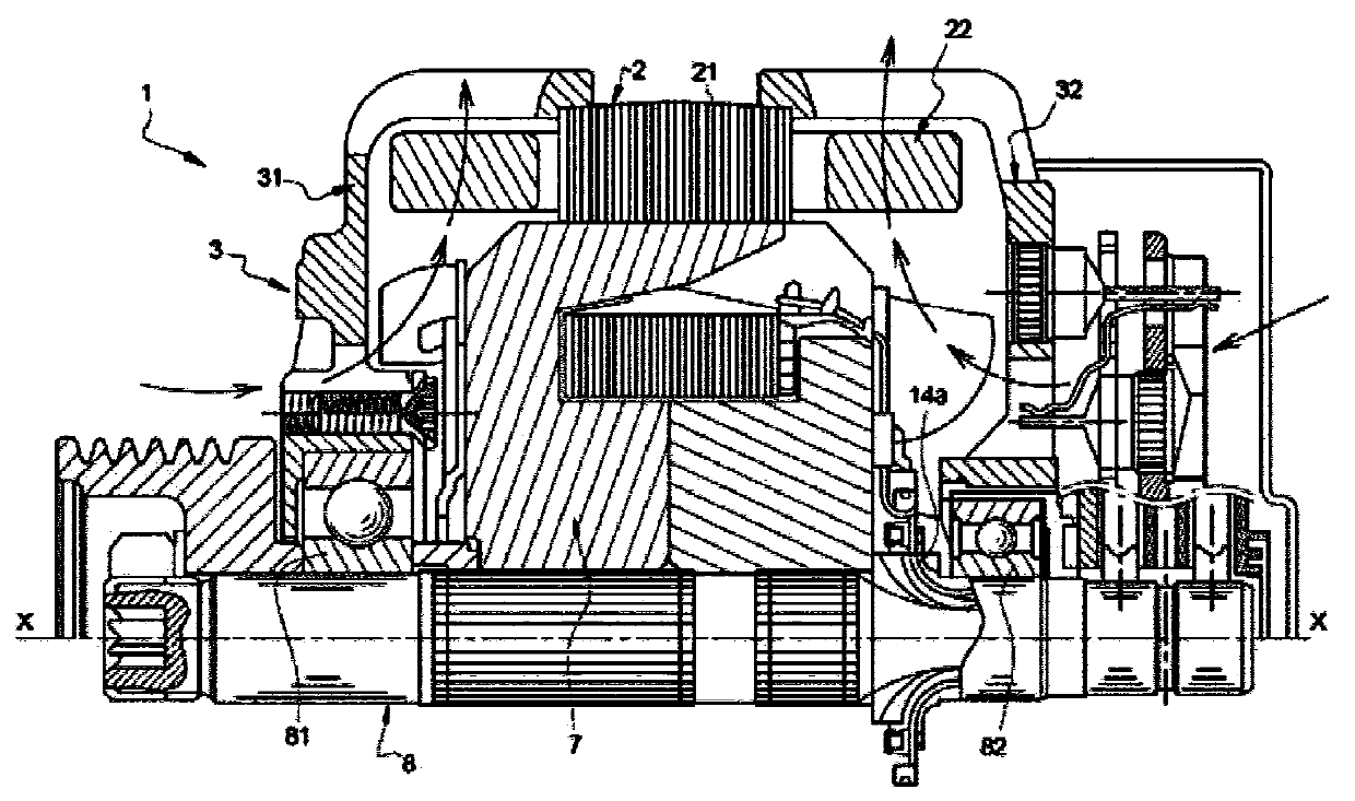
[0044] The invention relates to a rotating electrical machine 1 , in particular for a motor vehicle. The rotating electric machine 1 according to the invention may be in the form of an alternator, an electric motor or a reversible electric machine capable of operating in two modes.

[0045] figure 1 The overall structure of the rotating electric machine 1 is schematically shown.

[0046] refer to figure 1 A rotating electric machine 1 includes a stator 2 and a rotor 7 fitted on a shaft 8 . The shaft 8 is mounted for rotation about the axis of rotation X by means of bearing means 81 and 82 , for example ball bearings. The bearing devices 81 and 82 are supported by the rear support 31 and the front support 32 forming the housing 3 of the rotary electric machine 1 .

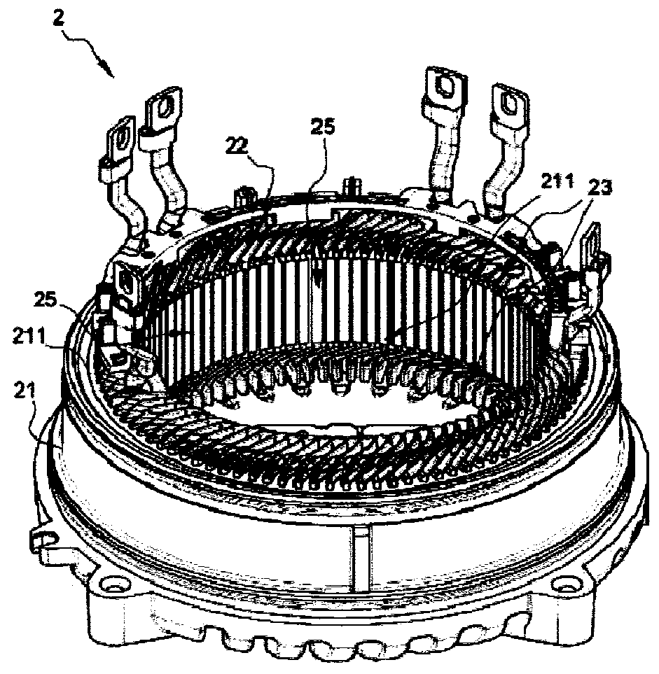
[0047] The stator 2 comprises a main body 21 , supported by the housing 3 , in the form of a stack o...


PUM


Abstract

The invention concerns a rotating electrical machine, in particular for a motor vehicle, comprising: a stator body, a stator winding carried by the stator body, a winding lead-out wire (23) protrudingwith respect to an end (211) of the stator body, a housing, carrying the stator body, comprising a bearing (31) positioned opposite the winding lead-out wire (23) of the stator, a sensor (4), a wedging element (5) positioned on a top portion (311) of the bearing (31), said wedging element (5) being constructed and arranged to compress the sensor (4) against the winding lead-out wire (23).

Description

technical field [0001] The invention relates to the general field of motor vehicles. More specifically, the invention relates to a rotating electric machine of a motor vehicle comprising a sensor, such as a temperature sensor, and elements for wedging the sensor in the winding bun of the electric machine. A rotating electric machine is for example an alternator, an electric motor or a reversible electric machine which can operate in two modes. Background technique [0002] Rotating electrical machine 1 (an example of which is in figure 1 ) includes a stator 2 and a rotor 7, the rotor 7 is separated from the stator 2 by an air gap (not shown). The rotor 7 is integral with a shaft 8 rotating about an axis X of rotation. Furthermore, the housing 3 supports the stator 2 and comprises at least one rear flange (referred to as rear support 31 ) and a front flange (referred to as front support 32 ). [0003] exist figure 2 The stator 2 , shown more clearly in , comprises a bod...

Claims


Application Information

Patent Timeline
IPC IPC(8): H02K11/25
CPCH02K11/25
Inventor F.鲍西科特
Owner VALEO EQUIP ELECTRIC MOTEUR
Features
  • Generate Ideas
  • Intellectual Property
  • Life Sciences
  • Materials
  • Tech Scout
  • Unparalleled Data Quality
  • Higher Quality Content
  • 60% Fewer Hallucinations
Learn More