Self-locking device suitable for endoscope

A self-locking device and endoscope technology, applied in the medical field, can solve the problems of low device usage, inconvenient use, and easy damage, and achieve obvious self-locking effect, prolong life, and save parts

Pending Publication Date: 2020-05-29
HUNAN VATHIN MEDICAL INSTR CO LTD
View PDF0 Cites 3 Cited by
  • Summary
  • Abstract
  • Description
  • Claims
  • Application Information

AI Technical Summary

Problems solved by technology

[0004] (1) The medical staff who need to operate have been pressing the dial with their hands, because it cannot be self-locked, so it is inconvenie

Method used


Image

  • Self-locking device suitable for endoscope
  • Self-locking device suitable for endoscope
  • Self-locking device suitable for endoscope

Examples


Example Embodiment

[0038] Example 1

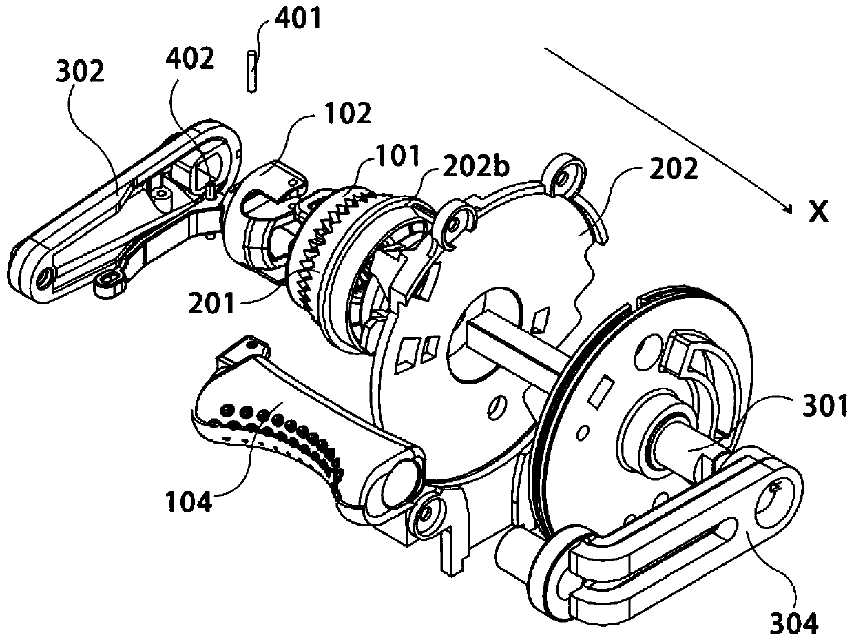
[0039] refer to Figure 1 to Figure 7 , the present invention provides a self-locking device suitable for an endoscope. In the first embodiment of the present invention, its main body includes a connecting component 100 and a matching component 200, and the connecting component 100 and the matching component 200 interact with each other. , to achieve self-locking and non-self-locking states.

[0040] Specifically, the connection assembly 100 includes a driven gear 101 and a toggle lever 102, and the driven gear 101 and the toggle lever 102 are matched by pins 401, so that when the toggle lever 102 moves, the driven gear 101 can achieve relative The left and right movement of the matching component 200 (here "left and right" is relative to the orientation in the figure, for the sake of clarity, the positive direction of the x-axis in the figure is defined as "right", and the following uses "left" or "right" to describe, not Repeatedly), so as to achieve a s...

Example Embodiment

[0047] Example 2

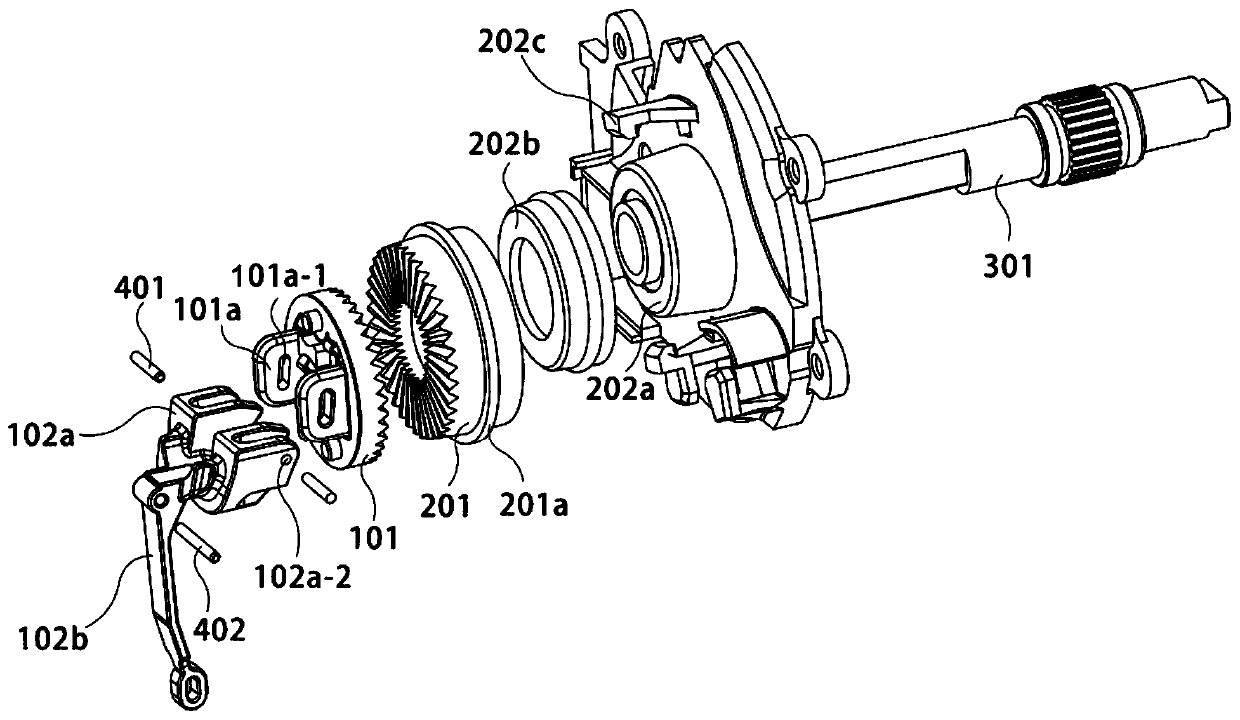
[0048] refer to Figure 1 to Figure 7 , the present invention provides a self-locking device suitable for an endoscope. In the second embodiment of the present invention, this embodiment is different from the first embodiment in that: in this embodiment, it also includes a fixed The assembly 300 includes a central shaft 301 and a positioning member 302, the driving gear 201 and the driven gear 101 are sequentially sleeved on the central shaft 301, the left limiting member 302 is fixed with the central shaft 301 by bolts, and the paddle 102b is connected by a pin shaft 402 is connected with the positioning member 302 .

[0049] Specifically, the connecting assembly 100 includes a driven gear 101 and a lever 102. The driven gear 101 includes a connecting protrusion 101a. The connecting protrusion 101a is provided with a limit hole 101a-1, and the horizontal direction of the limit hole 101a-1 is The shape of the cross section is a notch shape. The toggle lev...

Example Embodiment

[0058] Example 3

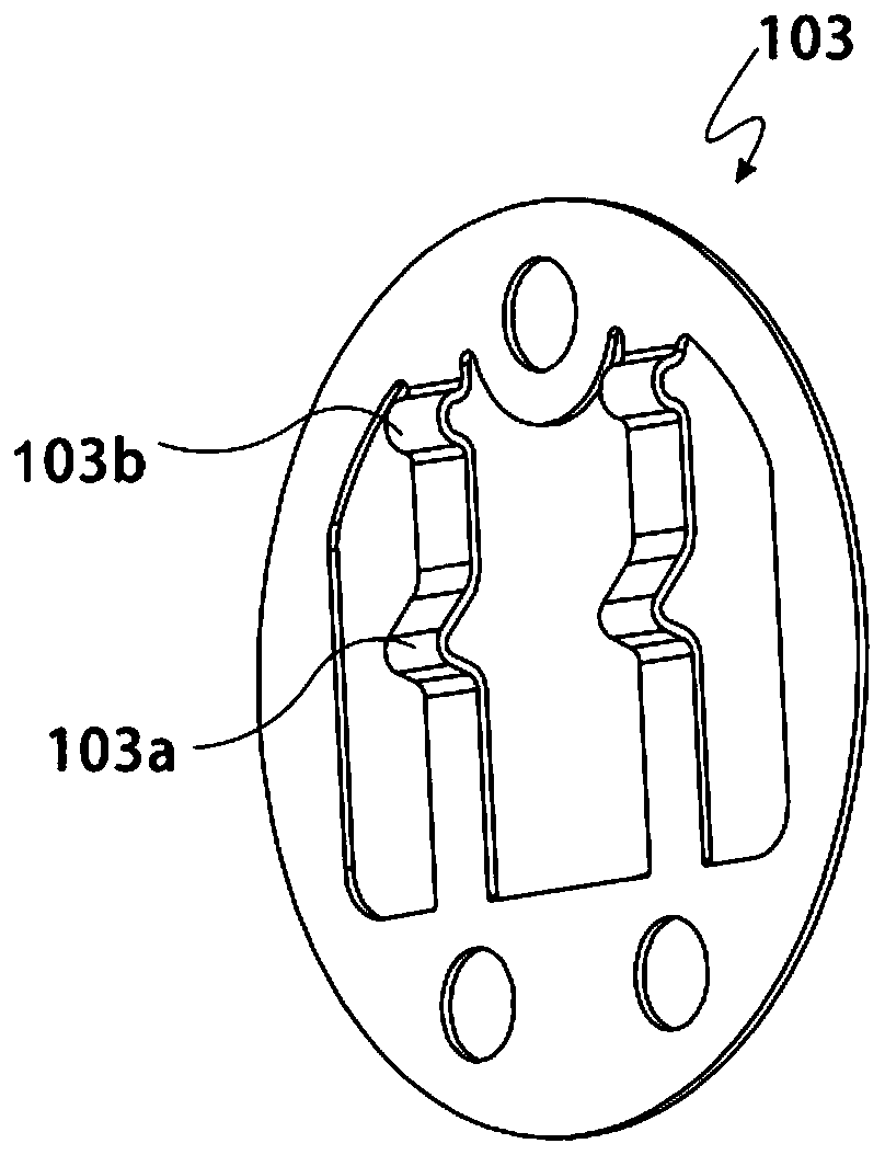
[0059] refer to Figure 1 to Figure 7 , the present invention provides a self-locking device suitable for an endoscope. In the third embodiment of the present invention, this embodiment is different from the second embodiment in that: in this embodiment, the connecting assembly 100 It also includes a spring sheet 103, which fits with the driven gear 101. The spring sheet 103 is provided with a first protrusion 103a, and the first protrusion 103a cooperates with the pressing protrusion 102a-3 on the gear connecting block 102a.

[0060] In order to facilitate understanding, the direction in the figure is taken as an example to illustrate. When the pressing protrusion 102a-3 is below the first protrusion 103a, the device is in a self-locking state; when the pressing protrusion 102a-3 When the device is above the first protrusion 103a, the device is in a non-self-locking state. Through the mutual cooperation of the pressing protrusions 102a-3 and the first pro...


PUM


Abstract

The invention discloses a self-locking device suitable for an endoscope. The self-locking device suitable for the endoscope comprises a connection assembly and a fitting assembly, wherein the connection assembly comprises a driven gear and a poking rod, and the driven gear and the poking rod match through a pin; and the fitting assembly comprises a driving gear, and the driving gear and the drivengear are meshed through the poking rod. The self-locking device suitable for the endoscope has the advantages that through occlusion of the driven gear and the driving gear, self-locking is achieved,so that a self-locking effect is obvious; and by designing a lever structure, switching of occlusion and separation of the driven gear and the driving gear can be achieved without external force of apart, so that not only is the part omitted, but also the service life of the device is prolonged.

Description

technical field [0001] The invention relates to the technical field of medical treatment, in particular to a self-locking device suitable for an endoscope. Background technique [0002] Endoscopes are widely used as current medical instruments. When medical personnel use it, they control the position of the lens of the endoscope in the human body by moving the handle. When doing experiments or operations, they generally see the internal structure of the human body, but also pay attention not to loosen it. Endoscope manipulation in hand. [0003] Therefore, there are several defects in the device of the endoscope on the market: [0004] (1) The medical staff who need to operate have been pressing the dial with their hands, because it cannot be self-locked, so it is inconvenient to use; [0005] (2) The parts that realize self-locking (for example, the brake principle) are easy to wear or break, so that the utilization rate of the device is low. Contents of the invention ...

Claims


Application Information

Patent Timeline
IPC IPC(8): A61B1/005A61B1/00
CPCA61B1/00066A61B1/0052A61B1/00042
Inventor 不公告发明人
Owner HUNAN VATHIN MEDICAL INSTR CO LTD
Why Eureka
Try Eureka