
Objective table for detecting hardness of ring type part, micro hardness tester and detecting method thereof

A technology of microhardness and stage, applied in the field of stage, can solve the problems of difficult detection work, time-consuming and distracting, and the detection piece is easy to be touched and moved, so as to prevent axial movement and achieve good self-locking effect. , Improve the effect of clamping reliability

Pending Publication Date: 2019-06-07
JIMEI UNIV
View PDF2 Cites 1 Cited by
  • Summary
  • Abstract
  • Description
  • Claims
  • Application Information

AI Technical Summary

Problems solved by technology

However, since the circumferential hardness test requires the center of the test piece to coincide with the rotation center of the stage, because there is no positioning and clamping device for the test piece, it is time-consuming to find the center coincidence position of the test piece, and the test piece is easy to be touched Touch and move, making it difficult to carry out subsequent testing work, and thus unable to accurately obtain the circumferential hardness distribution of the test piece

Method used


Image

  • Objective table for detecting hardness of ring type part, micro hardness tester and detecting method thereof
  • Objective table for detecting hardness of ring type part, micro hardness tester and detecting method thereof
  • Objective table for detecting hardness of ring type part, micro hardness tester and detecting method thereof

Examples


Embodiment Construction

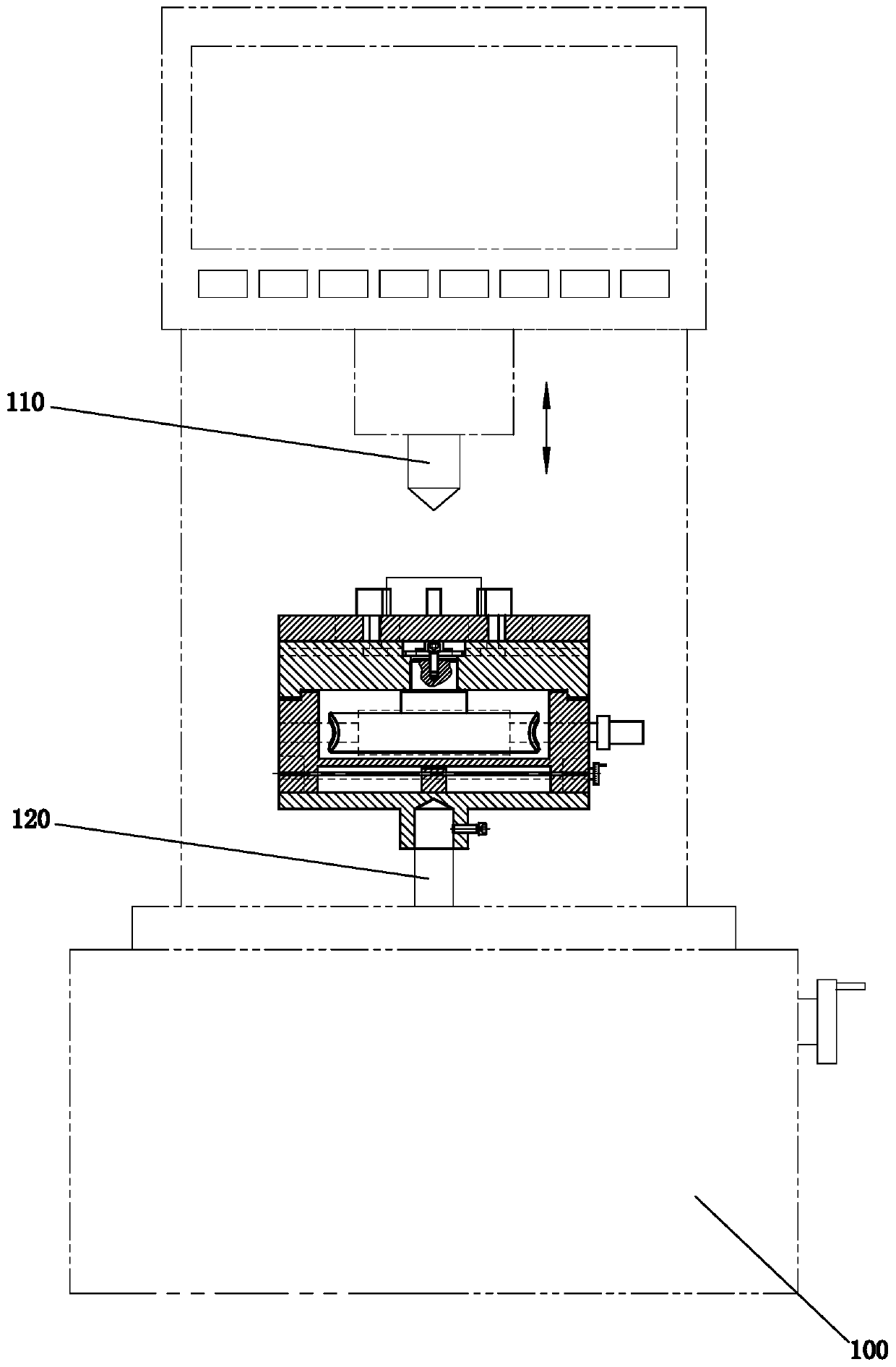
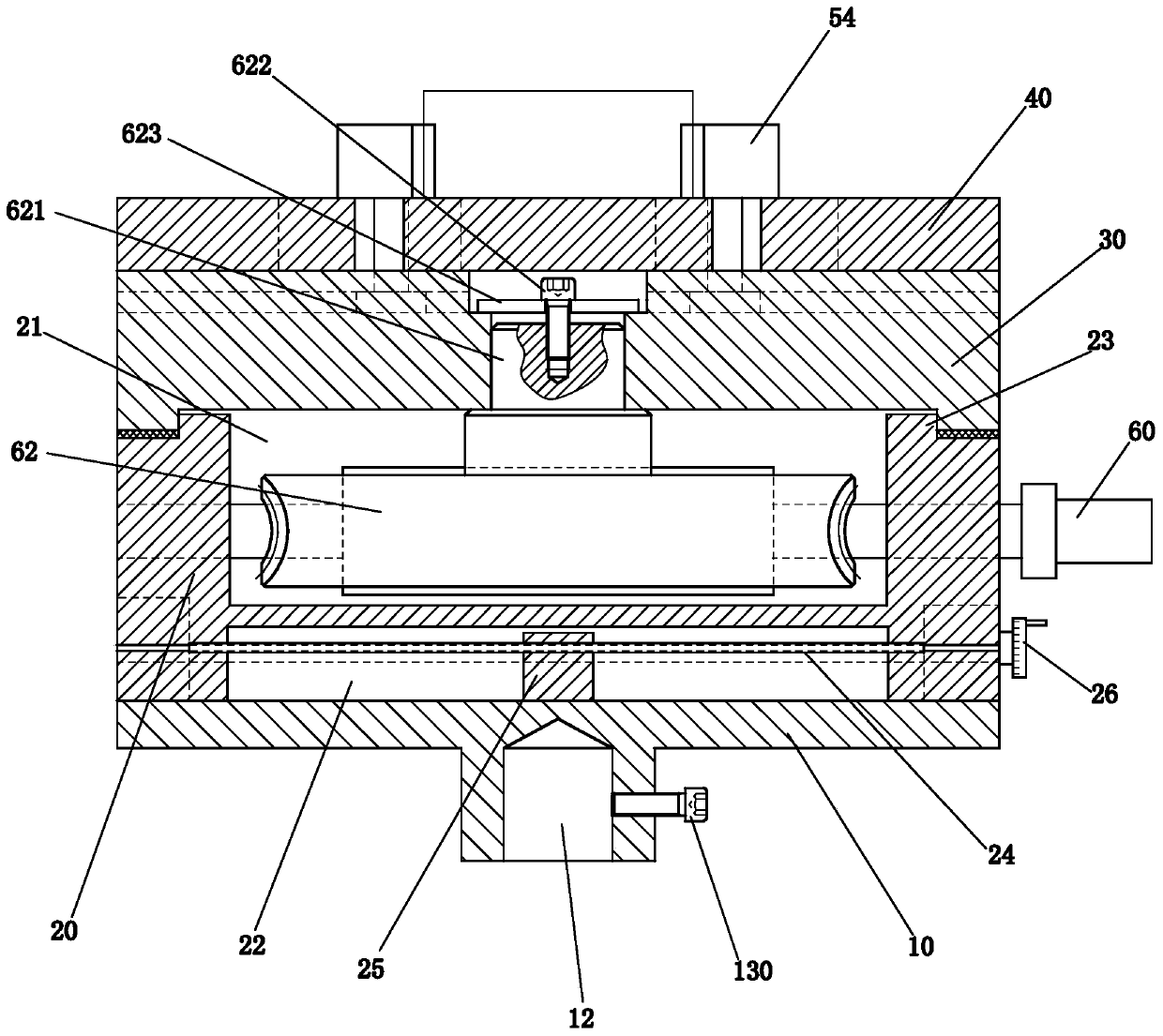
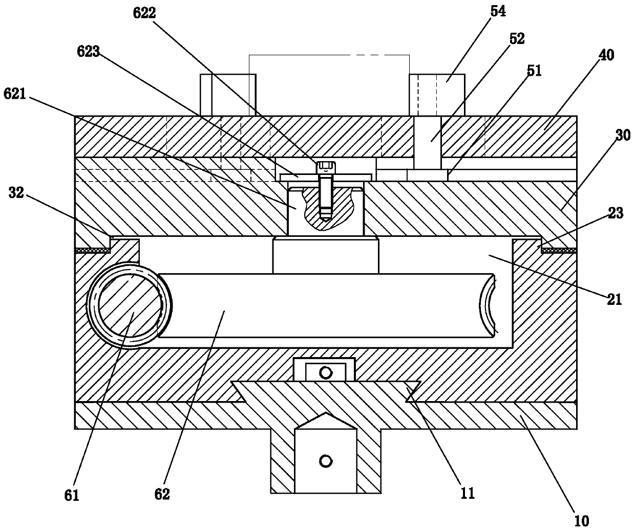
[0047] Please check Figure 2 to Figure 11 , a preferred embodiment of the stage used for hardness detection of ring parts, the described stage for hardness detection of ring parts includes a base part, a guide groove disc 30, an eccentric groove disc 40 and a positioning Locking member 50.

[0048] In this embodiment, the base part includes a base 10 and a horizontal worktable 20 that can move laterally along the base 10 , and the horizontal worktable 20 is located above the base 10 .

[0049]The top surface of the horizontal table 20 is provided with an assembly cavity 21, and the bottom surface is provided with an installation groove 22, and the top surface of the horizontal table 20 is provided with a round platform protrusion 23, and the center of the circular table protrusion 23 coincides with the center of the horizontal table 20. . like figure 2 As shown, the base 10 and the horizontal worktable 20 adopt a screw nut transmission mechanism for transmission cooperati...


PUM


Abstract

The invention discloses an objective table for detecting the hardness of a ring type part, a micro hardness tester and a detecting method thereof. The objective table comprises a base part, a guidinggroove disc, an eccentric groove disc, and a positioning locking piece. The guiding groove disc is installed at the base part in a rotating manner; and a guiding groove is formed in the top surface and extends in a length direction of a radius. The eccentric groove disc is connected to the guiding groove disc in a rotation manner; the eccentric groove disc and the guiding groove disc are arrangedconcentrically; and an eccentric groove is formed in the eccentric groove disc. The positioning locking piece passes through the eccentric groove and is in guiding fitting with the guiding groove. When a ring type part is placed on the top surface of the eccentric groove disc, the eccentric groove disc rotates to drive the positioning locking piece to approach the circle center of the eccentric groove disc along the guiding groove, so that the ring type part is clamped at the circle center of the eccentric groove disc by the positioning locking piece. According to the objective table, the overlapping of the circle center of the ring type part and the rotation center of the objective table is kept all the time; the trouble of locating the circle center of the ring type part again for othermicro hardness measurement point determination is saved; and the circumferential hardness distribution of the ring type part is obtained accurately.

Description

technical field [0001] The invention relates to an object stage, a microhardness tester and a detection method for hardness detection of ring parts. Background technique [0002] The stage is a standard part of the microhardness tester. The existing stage of the microhardness tester can only be driven by the knob to move linearly in the X direction or the Y direction, and cannot perform rotational movement, and cannot detect the circumferential hardness distribution of ring parts. [0003] Publication No. CN203616526U, titled as a patent for a microhardness test stage with adjustable angle, or Chinese patent with publication No. CN203595859U, titled a microhardness test stage, the test piece is placed directly on the On the object stage, the rotation of the detection part is driven by the rotation of the object stage. However, since the circumferential hardness test requires the center of the test piece to coincide with the rotation center of the stage, because there is no...

Claims


Application Information

Patent Timeline
IPC IPC(8): G01N3/40G01N3/02
Inventor 刘菊东许志龙杨小璠侯达盘沈志煌高顺兴李煌
Owner JIMEI UNIV
Learn More