Dynamic pedicle screw neutral pressurization and limiting tool of dynamic pedicle screw

A pedicle screw and dynamic technology, applied in the field of human spine internal fixation device and its special installation tools, can solve the problems of loss of flexion or extension movement, loss of swing angle, obstruction of adjustment and control, etc., to avoid dynamic swing. Uncontrollable angle, reducing the incidence and degree of occurrence, and ensuring the effect of surgical quality

Pending Publication Date: 2020-05-29
董谢平
View PDF0 Cites 1 Cited by
  • Summary
  • Abstract
  • Description
  • Claims
  • Application Information

AI Technical Summary

Problems solved by technology

However, this static fixation method is not the most ideal fixation method, and it is not suitable for all patients who need pedicle screw-rod system fixation. Therefore, the theory of non-rigid fixation and the corresponding non-rigid fixation pedicle screw-rod fixation system have gradually emerged. Among them, the dynamic pedicle screw (hereinafter referred to as the dynamic screw) with a non-rigid connection between the screw seat and the screw body has also begun to be used clinically; the original intention of this type of "dynamic screw" design is: it is implanted The nail body in the vertebral body, after the connecting rod is locked by the screw plug, can still swing at a positive or negative angle (±∠) relative to the nail seat and the connecting rod, so as to maintain moderate flexion and extension activities of the segment fixed by the dynamic nail ; but because in the process of operation, when the adjacent vertebral body is stretched and clamped, it is limited by the position between the nail seat and the vertebral body, and it is impossible to use tools to directly act on the nail body, but can only be used as the traditional method. Like "fixed nails", the tools used can only act on the nail seat; this leads to a phenomenon that is criticized: because the nail body and the nail seat of the dynamic pedicle screw can swing relative to each other, when the tool only acts When it is in the nail seat, affected by soft tissue resistance such as the intervertebral disc and ligament, the front end of the nail body cannot move parallel to the nail seat synchronously, but stays in place temporarily, so that the coaxial relationship between the nail seat and the nail body is destroyed , the included angle appears; only when the spreading or clamping force exerted by the tool continues to act, so that the swing angle between the nail body and the axis of the nail seat reaches the design limit value, the lower end of the nail body can provoke the front edge of the vertebral body to move, resulting in The effect of stretching or clamping; in this way, the swing angle set by the dynamic nail will be completely lost, and the flexion or straightening movement mode in the flexion and extension function will be lost, and the extension or flexion range in the opposite direction will be doubled, that is, the fixed The segment can only swing at 0~2 times the design angle (0~2*∠)
Both results of excessive and insufficient range of motion violate the original intention of the design of the dynamic nail, and may have adverse effects on the human body, which cannot reflect the superior performance of the "dynamic nail", seriously affecting the actuality of the advanced concept of dynamic fixation. application
[0003] The reason for affecting the operation effect of "Dynamic Nail" and the popularization and application of "Dynamic Nail" may be that the developers have ignored the fact that the traditional pedicle screw-rod fixation system mostly adopts the method of inserting the connecting rod into the U-shaped open slot at the top of the nail base and The structural form of being locked and fixed by the screw plug causes the lower component to be blocked by the upper component and cannot be directly operated, that is, after the connecting rod is placed, it will prevent tools such as nail setters from adjusting the nail body below the connecting rod and control, so that the flexible connected nail body and the nail base cannot temporarily become rigidly connected when stretched or compressed

Method used


Image

  • Dynamic pedicle screw neutral pressurization and limiting tool of dynamic pedicle screw
  • Dynamic pedicle screw neutral pressurization and limiting tool of dynamic pedicle screw
  • Dynamic pedicle screw neutral pressurization and limiting tool of dynamic pedicle screw

Examples


Embodiment Construction

[0038] In order to make the technical problems, technical solutions and beneficial effects solved by the present invention clearer, the present invention will be further described in detail in conjunction with the following examples; it should be understood that in the description of the present invention, the terms "left and right", "up and down" The orientation or positional relationship indicated by ", etc. is based on the orientation or positional relationship shown in the drawings, and is only for the convenience of describing the present invention, rather than requiring that the present invention must be constructed and operated in a specific orientation, so it should not be construed as a limitation of the present invention .

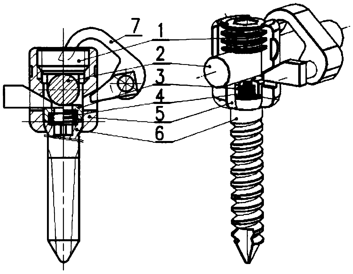
[0039] figure 1 , is the two-dimensional diagram and the effect diagram of the present invention; as can be seen from the diagram shown, what the present invention shows is basically two parts: one is the popular one based on the theory of "non-r...


PUM


Abstract

The invention discloses a dynamic pedicle screw provided with bayonets with wedge-shaped longitudinal sections on side walls of a screw seat and communicating with side walls as well as a limiting tool which can be edged in the bayonets and limit swing between the screw body and the screw seat by downwards extruding the head of the screw body to eliminate the current situations that as an existingdynamic pedicle screw rod fixing system cannot limit swing between a screw seat and a screw body in a surgery, the screw seat and the screw body cannot still be kept in a coaxial state after openingor pressurizing operation on a fixed section, and the instrument design original intention that the fixed section is still allowed to have flexion and extension movement in a certain range after fixation by the dynamic pedicle screw fixing system. The dynamic screw is temporarily fixed by the limiting tool to form a static screw with the screw body and the screw seat in rigid connection during thesurgery, so that the pedicle screw can apply force in a neutral position where the screw body and the screw seat do not swing at an angle, and after the limiting tool is removed after fixation is completed, the dynamic fixation function of the dynamic pedicle screw can be realized to the maximum extent.

Description

technical field [0001] The invention belongs to an internal fixation device for human spine and a special installation tool thereof. Background technique [0002] At present, in orthopedic surgery and neurosurgery, the pedicle screw and rod fixation system is often used to treat spinal injuries, degeneration, deformities, lesions and other injuries such as reduction, correction, and fixation. During the operation, after completing the implantation of all pedicle screws and installing the connecting rods, the spreader or clamper is often used to spread or clamp the screw seat of the pedicle screw first, so as to drive it to form a rigid structure with the screw seat. The connected nail body (hereinafter referred to as the fixation nail) is used to stir up the vertebral body fixed by the pedicle screw, so that the adjacent vertebral body and intervertebral space are opened or closed to the desired position, and then all the screw plugs are tightened to maintain the This posit...

Claims


Application Information

Patent Timeline
Patent Type & Authority Applications(China)
IPC IPC(8): A61B17/70
CPCA61B17/7001A61B17/7014A61B17/7035
Inventor 董谢平李青莉何伟义
Owner 董谢平
Why Eureka
Try Eureka