Collapsible catheter

A catheter and sheath technology, applied in the field of collapsible catheters, can solve the problems of stripped sheath breakage

Pending Publication Date: 2022-07-15
ABIOMED +1
View PDF0 Cites 0 Cited by
  • Summary
  • Abstract
  • Description
  • Claims
  • Application Information

AI Technical Summary

Problems solved by technology

This exemplary method is limited because the 14Fr stripping sheath has an inner diameter and a fracture line, so the physician must carefully consider the wall thickness and remaining available space when inserting the secondary 7Fr sheath to avoid breaking the stripping sheath

Method used


Image

  • Collapsible catheter
  • Collapsible catheter
  • Collapsible catheter

Examples


Embodiment Construction

[0019] In order to provide a thorough understanding of the systems, methods, and apparatuses described herein, certain illustrative embodiments will be described. Although the embodiments and features described herein are specifically described for use in conjunction with endovascular catheterization, it should be understood that all of the components and other features outlined below may be combined with each other in any suitable manner, and may be adapted and used in conjunction with Applies to other types of procedures that require catheters.

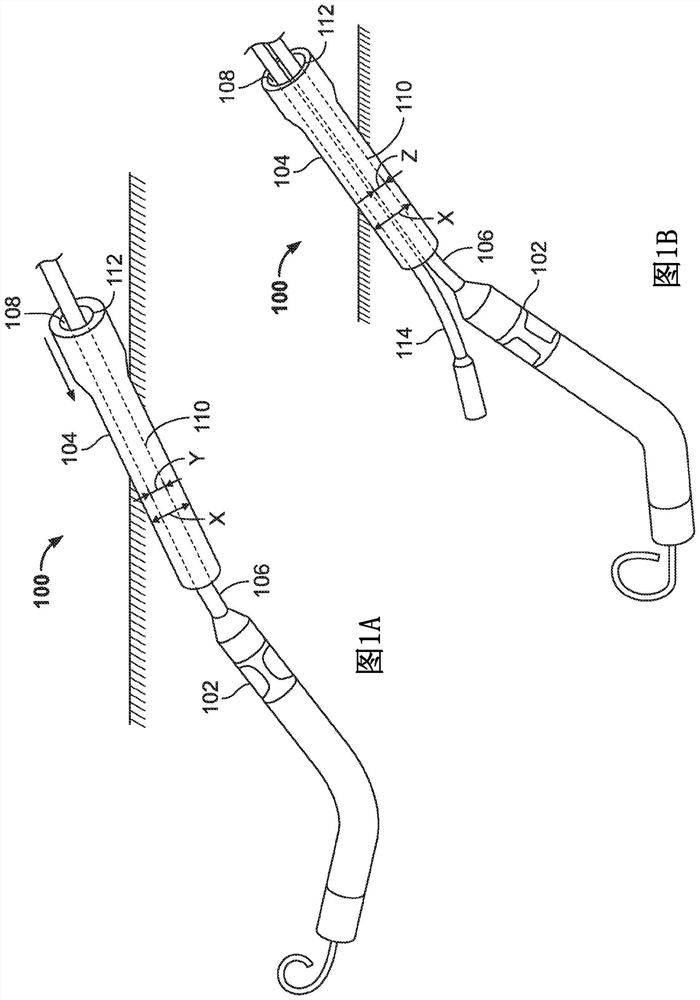
[0020] The term proximal should be understood to refer to a position on the catheter that is relatively closer to the operator during use of the catheter, while the term distal should be understood to refer to a position on the catheter that is relatively farther from the operator during use of the catheter. The term "upstream" should be understood to refer to a relatively more upstream position on the catheter in the blood flow wit...


PUM


Abstract

An intravascular system includes an introducer sheath (104) having a fixed diameter lumen, a first medical device (102), and a catheter (106) having a proximal end and a distal end coupled to the first medical device. When the catheter is positioned within the introducer sheath, an annular gap is formed between the outer circumference of the catheter and the inner circumference of the lumen. The catheter is configured to adopt different dimensional configurations (y, z) such that the size of the catheter and the size of the annular gap are variable. The variability in size of the catheter allows another medical device to pass through the annular gap within the lumen. The catheter may passively change configuration as the second medical device passes adjacently, or change configuration through an active mechanism under the control of a physician.

Description

[0001] CROSS-REFERENCE TO RELATED APPLICATIONS [0002] This application claims priority to US Provisional Application No. 62 / 908,199, filed September 30, 2019, the contents of which are incorporated herein by reference. Background technique [0003] Physicians performing high risk percutaneous coronary intervention (HRPCI) currently use two separate locations for accessing the arterial system if the physician plans to use mechanical circulatory support. The first entry point is for PCI device insertion in the right femoral artery, radial artery or brachial artery, and the second point is for blood pump insertion in the left femoral artery. Using two entry points, physicians face several disadvantages, including additional time to perform two insertions, greater chance of complications during surgery, access to require more introducers and closure devices, and inability to treat certain patients (eg, patients with vascular problems) are more likely. Vascular problems such as...

Claims


Application Information

Patent Timeline
Patent Type & Authority Applications(China)
IPC IPC(8): A61M25/00A61M25/06
CPCA61M25/0023A61M25/0662A61M2025/0024A61M60/13A61M60/216A61M60/865A61M25/0043A61M25/005A61M25/0045A61M25/0668A61M60/857A61B17/22A61M2025/0025A61M2205/0238A61B2017/22051A61B2017/22067
Inventor G·R·范图奇
Owner ABIOMED
Why Eureka
Try Eureka