Pistons for internal combustion engines

An internal combustion engine and piston technology, applied in the field of internal combustion engines, can solve problems such as ignition belt rupture and pressure fluctuation amplification, and achieve the effect of reducing the risk of rupture

Active Publication Date: 2022-04-12
MAHLE INT GMBH
View PDF6 Cites 0 Cited by
  • Summary
  • Abstract
  • Description
  • Claims
  • Application Information

AI Technical Summary

Problems solved by technology

[0005] However, in a gap of this type, which narrows between the ignition strip and the cylinder wall from the piston head to the first annular groove, it is disadvantageous that the pressure fluctuations flowing into said gap are further amplified
In some cases, pressure spikes, especially in so-called low speed pre-ignition (LSPI) conditions, are created by said amplified pressure fluctuations, which potentially increase the bursting of the ignition strip upwards and thus into the combustion chamber, Or the risk of a downward rupture of the ignition strip located between the first and second annular grooves, which must be avoided at all costs

Method used


Image

  • Pistons for internal combustion engines
  • Pistons for internal combustion engines
  • Pistons for internal combustion engines

Examples


Embodiment Construction

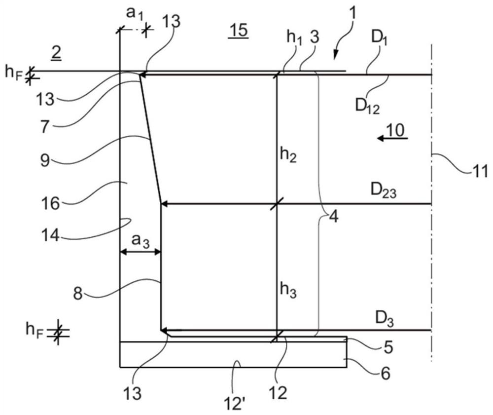
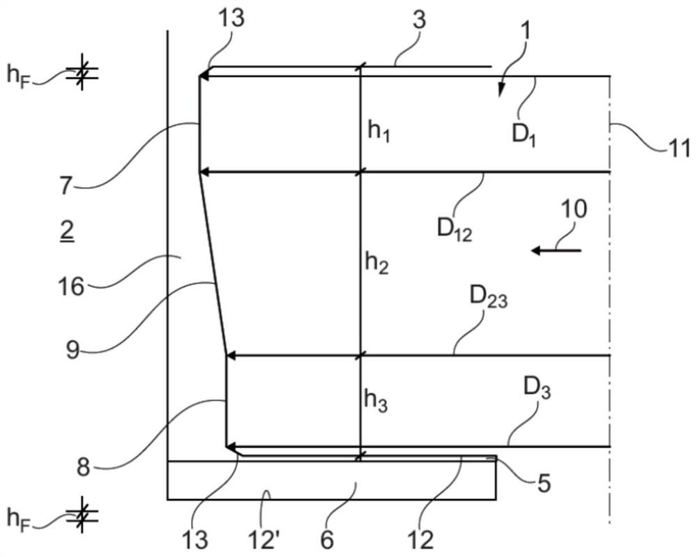
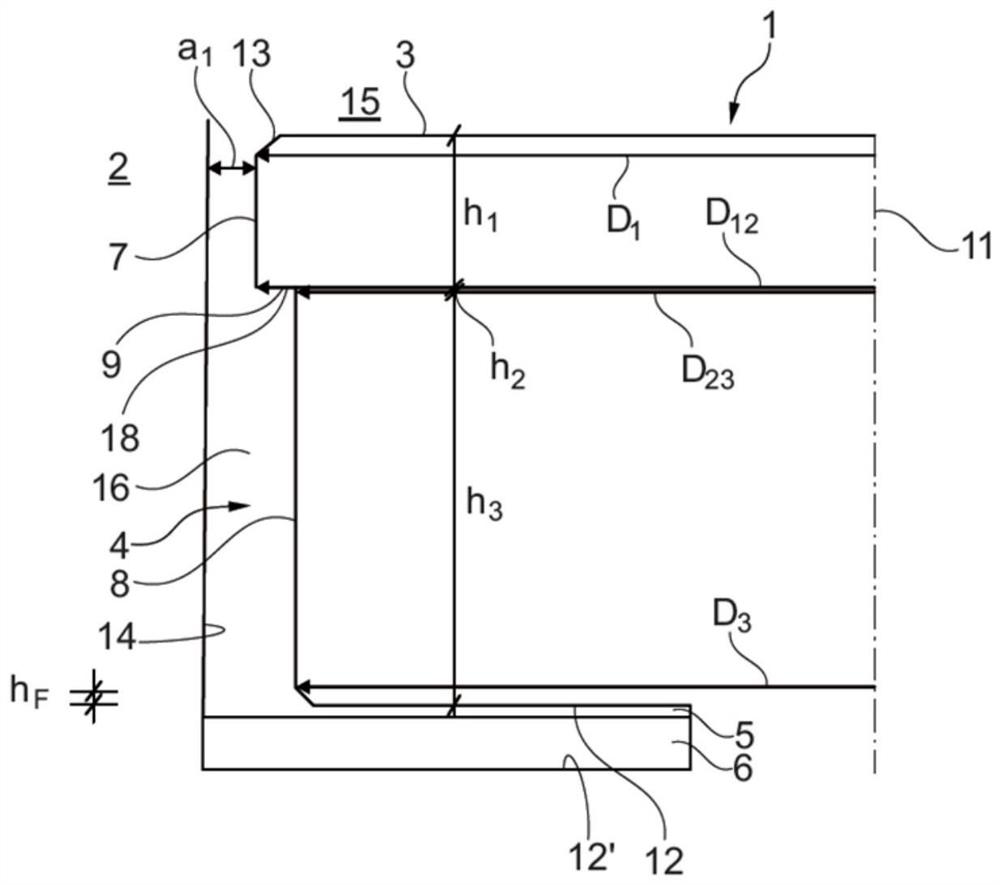
[0029] corresponds to Figure 1 to Figure 6 A piston 1 according to the invention for an internal combustion engine 2 comprises a piston head 3 , a surrounding ignition band 4 and at least one annular groove 5 adjoining the ignition band for receiving a piston ring 6 . Now provided according to the invention is a first ignition band part 7 adjacent to the piston head 3, a third ignition band part 8 adjacent to the annular groove 5 and a second ignition band part 9, the second ignition band part 9 connecting the two The ignition strip parts 7, 8 are arranged between them. The annular groove 5 has groove sides 12, 12', preferably parallel to the piston axis 11 and extending in a radial direction 10, in particular a groove side 12 of the proximal end of the piston head and a distal end of the piston head. 12' of groove sides. The first ignition strip part 7 has an axial height h 1 , the second ignition strip portion 9 has an axial height h 2 , the third ignition strip portion...


PUM


Abstract

The invention relates to a piston (1) comprising a piston head (3), a surrounding ignition band (4) and at least one annular groove (5). Crucial to the invention herein are: the first ignition band portion (7) adjacent to the piston head (3), the third ignition band portion (8) adjacent to the annular groove (5) and the connection between the two ignition bands. band parts (7,8) and a second ignition band part (9) arranged between them; the first ignition band part (7) has an axial height h 1 , the second ignition zone portion (9) has an axial height h 2 , and the third ignition zone portion (8) has an axial height h 3 ; The first ignition zone part (7) has an upper outer diameter D 1 , the third ignition zone portion (8) has a lower outer diameter D 3 , where the piston (1) has an outer diameter D at the transition from the first ignition band portion (7) to the second ignition band portion (9) 12 , and has an outer diameter D at the transition from the second ignition zone portion (9) to the third ignition zone portion (8) 23 ; apply (D 12 -D 23 ) / h 2 >(D 23 -D 3 ) / h 3 Be applicable. In view of this, especially negative LSPI effects can be reduced.

Description

technical field [0001] According to the preamble of claim 1, the invention relates to a piston for an internal combustion engine comprising a piston head, a surrounding ignition band and at least one annular groove for receiving a piston ring And adjacent to the ignition zone. Furthermore, the invention relates to an internal combustion engine having at least one such piston. Background technique [0002] Pistons of conventional type are well known, wherein the outer diameter from the piston head to the first annular groove is usually arranged on the fire land of said piston, the gap between the fire land and the cylinder wall being increased due to this outer diameter. Larger and narrower from the piston head to the first annular groove. It goes without saying that cylindrical ignition strips are also known. This can be achieved by means of a conical or cylindrical ignition zone of this type, for example with a larger chamfer at the transition from the ignition zone to t...

Claims


Application Information

Patent Timeline
Patent Type & Authority Patents(China)
IPC IPC(8): F02F3/00
CPCF02F3/00F02F5/00F16J9/22F16J1/09F16J9/20F02F2001/006F16J9/08
Inventor 克里斯托弗·贝伦斯
Owner MAHLE INT GMBH
Why Eureka
Try Eureka