Numerical control punching machine force increasing device capable of shortening punching time

A technology of CNC punching machine and force boosting device, which can be used in stripping devices, metal processing equipment, forming tools, etc., and can solve problems such as sheet or hole deformation, affecting product quality, etc.

Active Publication Date: 2020-05-29
广州精飞辉五金制品有限公司
View PDF6 Cites 0 Cited by
  • Summary
  • Abstract
  • Description
  • Claims
  • Application Information

AI Technical Summary

Problems solved by technology

[0005] In order to solve the above-mentioned technical problems, the present invention provides a force booster for a CNC punching machine that reduces the punching time, so as to solve the problem that the existing CNC equipment used when punching a workpiece similar to the above-mentioned plate, the punch presses down and punches the plate. After the hole parts are made, although the plate is fixed on the material rack of the numerical control equipment, there will be a pneumatic clamping device to fix the plate so that it will not move when it is punched. After the head passes through the plate, the machine head where it is located will press against the plate and form a tight fit with the plate. When the machine head goes up again after punching, it will bring the plate upward due to the tightness just now, and at this time it will rise randomly. When the raised punch reaches the top surface of the plate hole, it will also draw an upward pulling force on the plate, which will cause deformation of the plate or the hole and affect the quality of the product.

Method used


Image

  • Numerical control punching machine force increasing device capable of shortening punching time
  • Numerical control punching machine force increasing device capable of shortening punching time
  • Numerical control punching machine force increasing device capable of shortening punching time

Examples


Embodiment

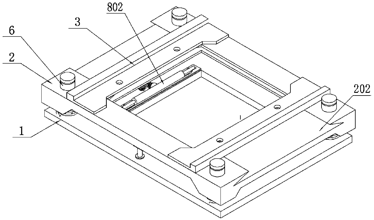
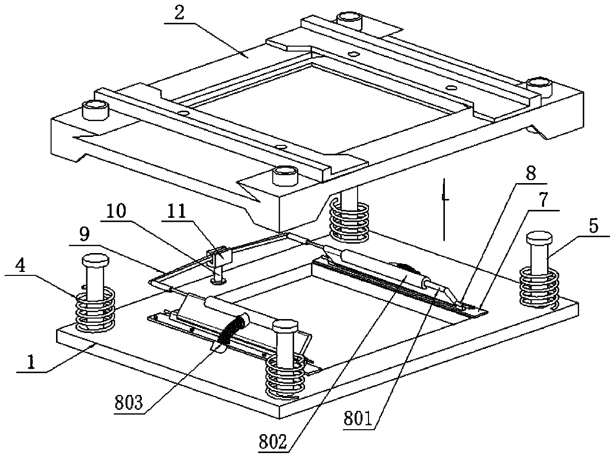
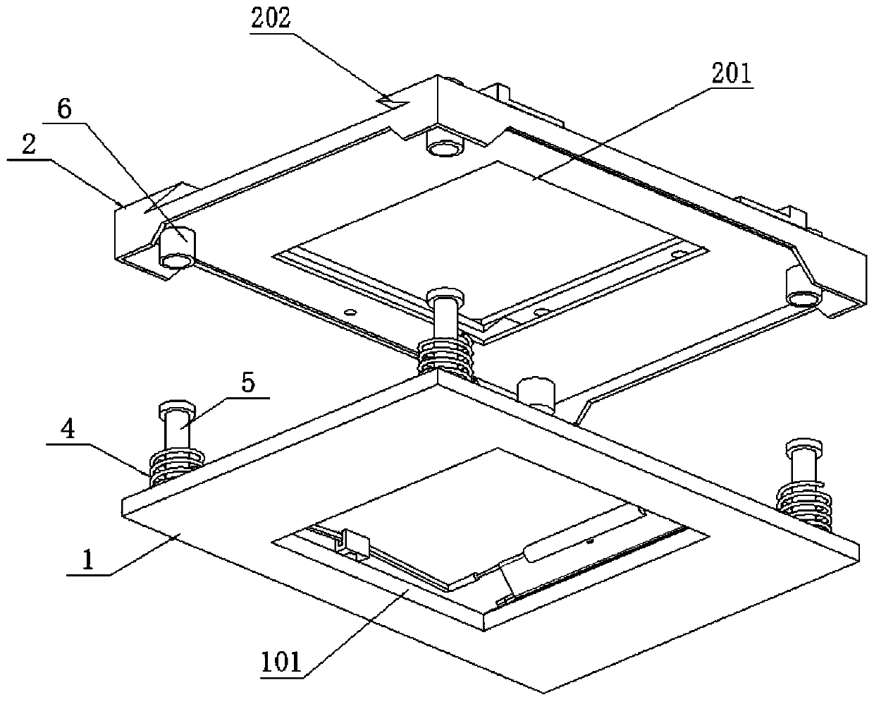
[0031] as attached figure 1 to attach Figure 8 Shown:

[0032] The present invention provides a kind of force boosting device for numerically controlled punching machine which can reduce the stamping time, which comprises a stripping bottom plate 1, a top seat 2 and a punch head fixing plate 3; The guide post 5 of the cap structure, a cylindrical spring 4 is also set on the four guide posts 5; a guide sleeve 6 runs through the four corners of the top seat 2, and the top seat 2 passes through these four guide posts. The sleeve 6 is slidably fitted on the stripping bottom plate 1, and the top seat 2 forms spring contact with the four springs 4 on the stripping bottom plate 1. Bottom grooves 101 are respectively provided on the stripping bottom plate 1 at the bottom and the top seat 2 at the top. and the top groove 201, the two stamping head fixing plates 3 are located on both sides of the top groove 201, thus as figure 2 , image 3 as well as Figure 4 As shown, it can be...


PUM


Abstract

The invention provides a numerical control punching machine force increasing device capable of shortening punching time. The device comprises a material returning bottom plate, a top seat and punchingmachine head fixing plates, wherein four guide columns with limiting cap structures at the top ends are evenly distributed and arranged at four corners of the bottom face of the material returning bottom plate correspondingly, the each guide column is further sleeved with a corresponding cylindrical spring, a corresponding guide sleeve penetrates through each of four corners of the top seat, thetop seat is in sliding fit with the material returning bottom plate through the four guide sleeves, the top seat is in elastic contact with the four springs on the material returning bottom plate, thepunching machine head fixing plates comprise the left punching machine head fixing plate and the right punching machine head fixing plate which are both L-shaped bent plate structures, oiling coolingtreatment is carried out on the surfaces of machine heads moving up and down in the working process, oiling cooling is carried out according to the working intensity of the machine heads, downward pulling adjustment is carried out after the machine heads are abraded to a certain degree in a pressure adjusting mode, and a wiping base on the inner side of a rotating plate can be frequently used, sothat the service life can be prolonged.

Description

technical field [0001] The invention belongs to the technical field of accessories for CNC punching machines, and more specifically relates to a force booster for CNC punching machines that reduces punching time. Background technique [0002] CNC punching machine is the abbreviation of digital control punching machine, which is an automatic machine tool equipped with a program control system. The control system can logically process programs with control codes or other symbolic instructions, and decode them, so that the punching machine can move and process parts. Among them, the CNC punching machine for plate workpieces is widely used, and a machine head is installed. Or multiple punches, the direction of the machine head is controlled through the programming program of the numerical control system, and the punch on the machine head is used to punch down to punch out the punching track corresponding to the program on the surface of the plate. [0003] The CNC punching mach...

Claims


Application Information

Patent Timeline
IPC IPC(8): B21D28/26B21D37/16B21D45/02
CPCB21D28/26B21D37/16B21D45/003B21D45/02
Inventor 郝玲
Owner 广州精飞辉五金制品有限公司
Why Eureka
Try Eureka