
A milling and drilling all-in-one machine

An all-in-one machine and milling technology, which is applied in the field of machine tools, can solve the problems of time-consuming, etc., and achieve the effect of good clamping effect and simple blanking

Active Publication Date: 2021-07-20
蓝海五金(深圳)有限公司
View PDF8 Cites 0 Cited by
  • Summary
  • Abstract
  • Description
  • Claims
  • Application Information

AI Technical Summary

Problems solved by technology

[0004] The above existing technical solutions have the following defects: when in use, the printer shaft inside the feeding mechanism falls into the slot on the upper part of the sliding seat, the fixing piece fixes the printing shaft, and the drive assembly drives the sliding seat to move to the milling surface Milling is carried out at the mechanism. After the milling is completed, the driving component drives the sliding seat to move to the drilling mechanism for drilling. After the drilling is completed, the material is unloaded. After the completion, the sliding seat moves to the loading mechanism again. The entire production process requires each printer The next material can be processed only after the axis finishes milling and drilling, which takes a lot of time

Method used


Image

  • A milling and drilling all-in-one machine
  • A milling and drilling all-in-one machine
  • A milling and drilling all-in-one machine

Examples


Embodiment Construction

[0033] The present invention will be described in further detail below in conjunction with the accompanying drawings.

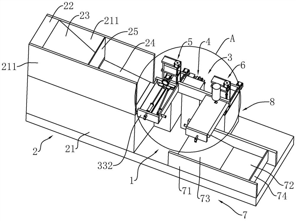
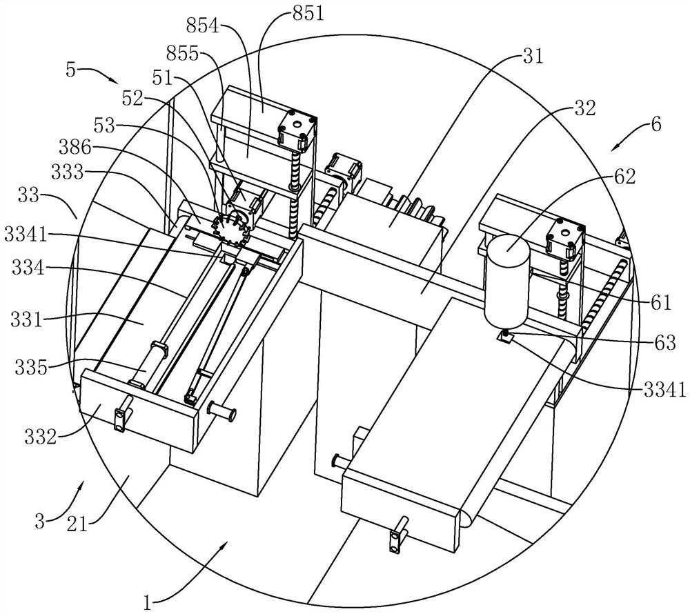
[0034] refer to figure 1 , is an integrated milling and drilling machine disclosed by the present invention, comprising a working panel 1, a feeding mechanism 2 arranged on the upper part of the working panel 1, a conveying mechanism 3 arranged on one side of the feeding mechanism 2, and a conveying mechanism 3 arranged on both sides of the conveying mechanism 3. The milling mechanism 5 and the drilling mechanism 6 on the side, and the receiving mechanism 7 arranged on the upper part of the working panel 1 .

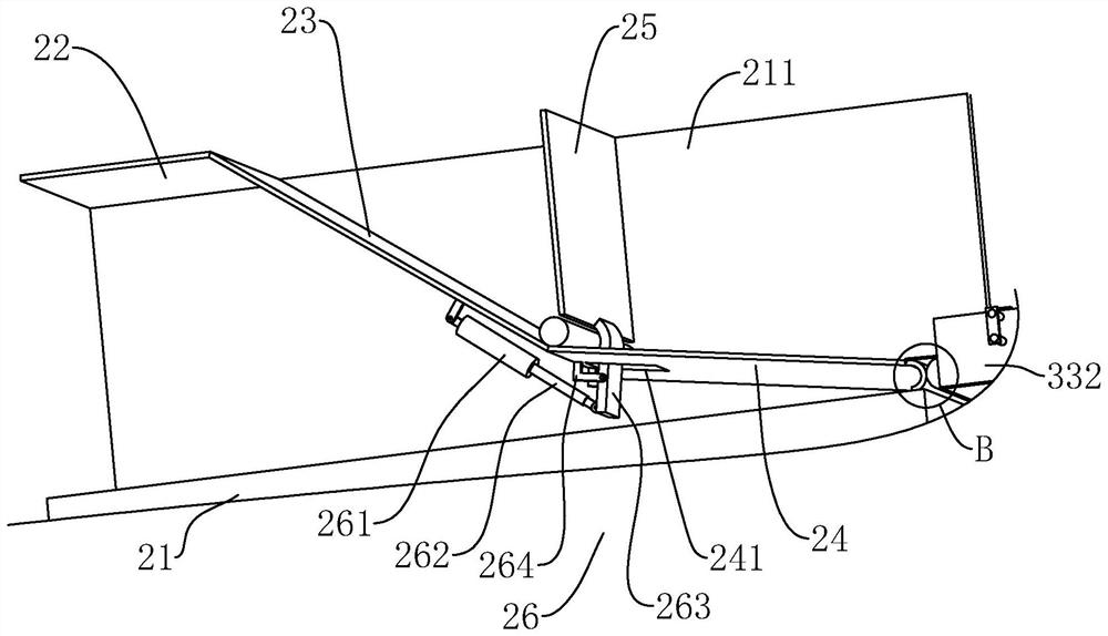
[0035] refer to figure 1 The feeding mechanism 2 includes a base 21 fixedly connected to the upper part of the working panel 1. The upper end surface of the base 21 is fixedly connected with a feeding riser 211 symmetrical to the center line along the length direction of the base 21. Between the two feeding risers 211 A first plate 22 arranged horizon...


PUM


Abstract

The invention discloses a milling and drilling integrated machine, which includes a conveying mechanism, the conveying mechanism includes a first mounting seat, a mounting plate mounted on one side of the first mounting seat through a driving mechanism, and the mounting plate is far away from the side of the first mounting seat There are two sets of placing components with the same structure fixedly connected; milling mechanisms and drilling mechanisms are respectively provided on both sides of the first mounting seat; the placing components are 180-degree rotationally symmetrical along the center of the mounting plate; the placing components include fixed connections on the mounting plate away from The placement plate on one side of the first mounting seat, the placement groove provided on the top of the placement plate, the top of the placement plate is symmetrically provided with the first clamping block and the second clamping block along the center line of the extension direction of the placement groove, and the vertical height of the placement groove is less than One-half of the diameter of the material; the second clamping block clamps the material through the clamping assembly. The invention has the effect of reducing the time spent on processing the next material after the milling and drilling processes of a single material are not required in the production process.

Description

technical field [0001] The invention relates to the technical field of machine tools, in particular to an integrated milling and drilling machine. Background technique [0002] At present, the printer is a very important work equipment in the current office, and the printer shaft is an important component in the printer. In order to make the axis of the printer meet the needs of actual use, the printer is usually in the shape of a long cylindrical rod, and its surface is slotted, drilled, milled, bored, etc. to facilitate its installation and use, slotting, milling, Processes such as drilling or boring are usually carried out on automatic processing machines, which are convenient, labor-saving, fast and efficient. [0003] Existing, the Chinese utility model patent that notification number is CN209453131U discloses a kind of printer shaft center automatic machining bed, comprises frame and is located on the feeding mechanism on the frame, milling mechanism, drilling mechani...

Claims


Application Information

Patent Timeline
Patent Type & Authority Patents(China)
IPC IPC(8): B23P23/02B23Q7/00B23Q3/08
CPCB23P23/02B23Q3/08B23Q7/00B23Q2703/04
Inventor 王人欢李志文李焰光
Owner 蓝海五金(深圳)有限公司
Learn More