
A wall polishing path planning method, device, equipment and medium

A path planning and path technology, which is used in grinding/polishing equipment, automatic grinding control devices, metal processing equipment, etc. It can solve the problem that the machine cannot accurately control the grinding depth, cannot guarantee the optimal grinding operation path, and the labor cost is high. question

Active Publication Date: 2020-08-14
GUANGDONG BOZHILIN ROBOT CO LTD
View PDF20 Cites 0 Cited by
  • Summary
  • Abstract
  • Description
  • Claims
  • Application Information

AI Technical Summary

Problems solved by technology

[0003] At present, the wall grinding machine is mainly used to grind the wall, but the machine cannot accurately control the grinding depth, and a second grinding is required manually, and the labor cost is relatively high
Moreover, the optimal grinding path cannot be guaranteed, and the grinding efficiency is low

Method used


Image

  • A wall polishing path planning method, device, equipment and medium
  • A wall polishing path planning method, device, equipment and medium
  • A wall polishing path planning method, device, equipment and medium

Examples


Embodiment 1

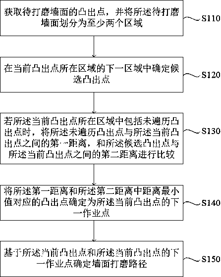
[0036] figure 1 It is a flow chart of a wall grinding path planning method provided by Embodiment 1 of the present invention. This embodiment is applicable to the grinding of protruding points on the wall, and the method can be executed by a wall grinding path planning device. Specifically Including the following steps:

[0037] S110. Obtain the protruding points of the wall surface to be polished, and divide the wall surface to be polished into at least two regions.

[0038] Generally, there will be protruding points on the wall of the construction building that exceed the acceptance standard. At this time, the protruding points need to be polished. Polish path planning. Optionally, dividing the wall surface to be polished into at least two areas includes: dividing the wall surface to be polished into at least two areas according to the size of the grinding equipment, and the width of the area is greater than the diameter of the grinding equipment . If the width of the ar...

Embodiment 2

[0057] Figure 6 It is a flow chart of a wall grinding path planning method provided by Embodiment 2 of the present invention. This embodiment is further optimized on the basis of the above embodiments. Optionally, the wall grinding path planning method further includes: for any convex Out of the point, a judgment grid is established, wherein, the judgment grid includes a contour line characterizing the decreasing diffusion trend of the protruding point, and the contour line of the protruding point diffusion trend can provide a basis for the judgment of the grinding direction; based on The contour line determines the single-point grinding path of the protruding point, which avoids uneven grinding and can make the polished wall more conform to the acceptance standard. Such as Figure 6 As shown, it specifically includes the following steps:

[0058] S210. Obtain salient points of the wall surface to be polished, and divide the wall surface to be polished into at least two reg...

Embodiment 3

[0069] Figure 9 A structural diagram of a wall grinding path planning device provided in Embodiment 3 of the present invention, the device includes: an area division module 310, a candidate salient point determination module 320, a distance comparison module 330, a next operation point determination module 340 and The grinding path determination module 350 .

[0070]Among them, the area division module 310 is used to obtain the salient points of the wall surface to be polished, and divide the wall surface to be polished into at least two areas; the candidate salient point determination module 320 is used to locate Determine the candidate salient point in the next area of ​​the area; the distance comparison module 330 is used to compare the untraversed salient point with the current salient point if the area where the current salient point is located includes an untraversed salient point. The first distance between the outgoing points is compared with the second distance betw...


PUM


Abstract

The embodiment of the invention discloses a wall grinding path planning method, device, equipment and medium. The method includes: obtaining the salient points of the wall surface to be polished, and dividing the wall surface to be polished into at least two areas; determining candidate salient points in the next area of ​​the area where the current salient points are located; if the current salient points When the area includes the untraversed salient point, compare the first distance between the untraversed salient point and the current salient point with the second distance between the candidate salient point and the current salient point; The protruding point corresponding to the minimum distance between the first distance and the second distance is determined as the next operating point of the current protruding point; the wall grinding path is determined based on the current protruding point and the next operating point of the current protruding point. The technical solution of the embodiment of the present invention solves the problem that the grinding path of the grinding equipment covers the area that does not need grinding at the present stage, realizes the effect of optimizing the working path of the grinding equipment, improving the grinding efficiency, and reducing the grinding cost.

Description

technical field [0001] Embodiments of the present invention relate to path planning technology, in particular to a wall grinding path planning method, device, equipment and medium. Background technique [0002] The main structure of the building at this stage is generally pouring type. Before plastering the wall, the wall needs to be polished so that the plastering layer can fully contact the wall and avoid hollowing or cracking on the plastered wall. Phenomenon. [0003] At this stage, the wall surface is mainly polished by a wall grinder, but the machine cannot accurately control the grinding depth, and a second grinding is required manually, and the labor cost is relatively high. Moreover, it is impossible to guarantee the optimal grinding path, and the grinding efficiency is low. Contents of the invention [0004] Embodiments of the present invention provide a wall grinding path planning method, device, equipment and medium, so as to optimize the grinding path and im...

Claims


Application Information

Patent Timeline
Patent Type & Authority Patents(China)
IPC IPC(8): B24B1/00B24B7/18B24B41/00B24B51/00G06F30/20
CPCB24B1/00B24B7/182B24B41/00B24B51/00G05B19/4207B25J9/1664G05B2219/45199G05B2219/49378E04F21/16
Inventor 袁皓男陈航英曹国舒远刘牟林何素韵张桐欣陶志成
Owner GUANGDONG BOZHILIN ROBOT CO LTD
Learn More