Coupler socket mechanical life detection device and method

A technology of mechanical life and detection devices, which is applied in the direction of hand-held tools and manufacturing tools, can solve the problems of high labor intensity for operators, inaccurate detection results, and inapplicability to the current production situation, etc., to achieve improved testing efficiency, large promotion range, The effect of improving test accuracy and efficiency

Pending Publication Date: 2020-05-29
GREE ELECTRICAL APPLIANCE SHIJIAZHUANG +1
View PDF0 Cites 1 Cited by
  • Summary
  • Abstract
  • Description
  • Claims
  • Application Information

AI Technical Summary

Problems solved by technology

However, the existing mechanical life test of the incoming goods inspection of the air-conditioning coupler socket still uses a relatively backward and inefficient manual detection test. Manually rotate the coupler plug and socket, the operation time is long (7000 operations), and the labor intensity of the operator is high
Moreover, manual detection is often accompanied by inconsistencies in detection accuracy, resulting in inaccurate final detection results that are not suitable for the current production status

Method used


Image

  • Coupler socket mechanical life detection device and method
  • Coupler socket mechanical life detection device and method

Examples


Embodiment 1

[0020] Embodiment 1: A coupler socket mechanical life detection device.

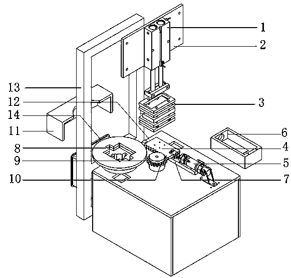
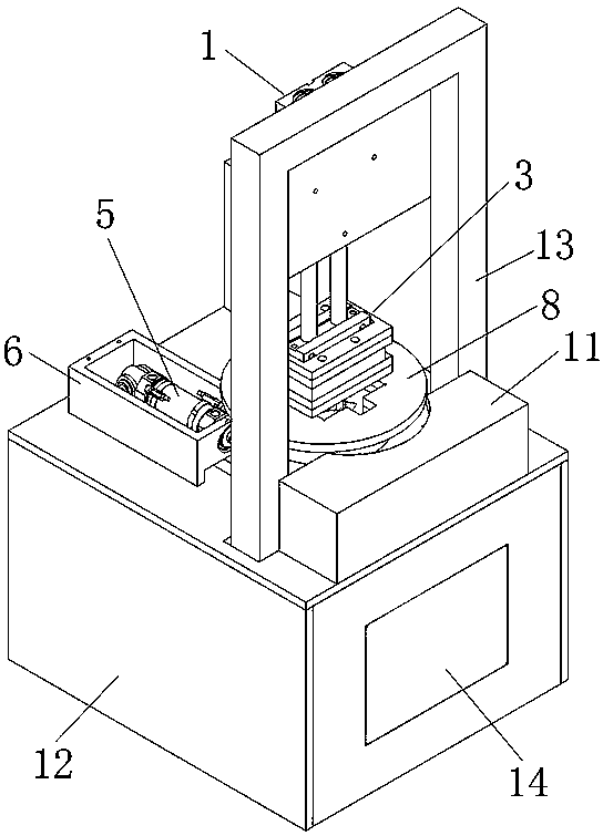
[0021] An automatic detection device for the mechanical life of a coupler socket includes four parts: a pressing and positioning mechanism, a pushing mechanism, a rotating mechanism, and a main body mechanism.

[0022] The pressing and positioning mechanism is used to assemble the plug to the coupler socket. The pressing and positioning mechanism includes a pressing cylinder 1, a pressing cylinder fixing plate 2 and a plug fixing plate 3. The pressing cylinder fixing plate 2 is arranged on the main body mechanism Above, the compression cylinder 1 is installed on the compression cylinder fixing plate 2, and the plug fixing plate 3 is installed on the bottom of the compression cylinder 1 push rod. The installation position of the compression cylinder fixing plate 2 can be adjusted up and down, and it is only necessary to adjust the up and down position of the compression cylinder 1 during the first commiss...

Embodiment 2

[0027] Embodiment 2: A method for detecting the mechanical life of a coupler socket.

[0028] A method for detecting the mechanical life of a coupler socket, the specific operation steps are as follows:

[0029] The operator picks up the coupler socket and puts it into the coupler socket fixing plate 8 to start "loading", and then the operator touches the "reset in place" button in the display 14, and the device will automatically reset. When the reset is in place, "reset" The "in place" button is displayed in green, otherwise it is red. Only when the operator presses the "start" button when the reset is in place can the device be tested, otherwise it will not act.

[0030] After the operator presses the "Start" button on the display screen, the cylinder 1 is pressed down, and the coupler plug can be accurately inserted into the coupler socket in the coupler socket fixing plate 8, simulating manual insertion of the plug into the socket. After the compression cylinder 1 is low...


PUM


Abstract

The invention provides a coupler socket mechanical life detection device and method. The coupler socket mechanical life detection device comprises a pressing and positioning mechanism, a pushing mechanism, a rotating mechanism and a main body mechanism; the pushing mechanism is mounted on the main body mechanism, the pushing mechanism is meshed and connected with the rotating mechanism, the pressing and positioning mechanism is arranged above the rotating mechanism, the pressing and positioning mechanism is used for connecting and mounting a coupler socket and a plug, and the pushing mechanismand the rotating mechanism are used for controlling rotation of the coupler socket. The coupler socket and the plug are positioned and accurately assembled through the pressing and positioning mechanism, the rotating action of the coupler socket is completed through cooperation of the pushing mechanism and the rotating mechanism, a traditional test mode is changed, automatic detection is realized, and the working efficiency and the detection precision are effectively improved.

Description

technical field [0001] The invention relates to the technical field of air-conditioning equipment detection, in particular to a device and method for detecting the mechanical life of a coupler socket. Background technique [0002] With the development of modern technology, more automation is applied to product testing. However, the existing air-conditioning coupler socket inspection mechanical life test still uses a relatively backward and low-efficiency manual inspection test. The test requires that "the mechanical life of the spring rotation inside the coupler socket is not less than 7000 times", and the operator needs Manually rotate the coupler plug and socket, the operation time is long (operating 7000 times), and the labor intensity of the operator is high. Moreover, manual detection is often accompanied by inconsistencies in detection accuracy, resulting in inaccurate final detection results that are not suitable for the current production status. Contents of the i...

Claims


Application Information

Patent Timeline
Patent Type & Authority Applications(China)
IPC IPC(8): B25B27/02
CPCB25B27/026
Inventor 李伟超赵会帅陈玉雄于思贺冯晓堤王宁宁朱家领祝少斌郭兆雷张玉龙张明王刚霍朋戎海梅胡耀华
Owner GREE ELECTRICAL APPLIANCE SHIJIAZHUANG
Why Eureka
Try Eureka