Eureka AIR delivers breakthrough ideas for toughest innovation challenges, trusted by R&D personnel around the world.

Novel hydraulic coupling device

A coupling device and hydraulic technology, which is applied in the field of coupling sleeves, can solve the problems of laborious disassembly, time-consuming installation and disassembly, and increased cost of use, and achieve the effects of convenient disassembly and maintenance, convenient torque adjustment, and good reliability

Pending Publication Date: 2020-05-29
浙江德成机械科技有限公司
View PDF0 Cites 0 Cited by
  • Summary
  • Abstract
  • Description
  • Claims
  • Application Information

AI Technical Summary

Problems solved by technology

[0003] The traditional connecting device of the coupling sleeve is connected by a key. The coupling sleeve and the shaft are each machined with key grooves, and the coupling sleeve and the shaft are connected by keys. According to the connection requirements, the keys are also divided into various types, and because The existence of the keyway on the shaft not only weakens the strength of the shaft, but also increases the processing difficulty and cost. In order to make the shaft have sufficient strength, it is generally necessary to increase the shaft diameter, resulting in an increase in the cost of use and an increase in the volume of the equipment.
Interference fit or transition fit is often used between the traditional keyed shaft and the mating surface of the coupling sleeve. The coupling sleeve needs to be heated during installation, and a professional puller is required for disassembly, which is time-consuming and laborious to install and disassemble.
[0004] For the coupling sleeve on the existing hydraulic coupling sleeve, since there is only one oil inlet chamber installed, the oil inlet chamber is not disassembled. When disassembling, high-pressure hydraulic oil is injected through the oil discharge hole, and the force acting on the cone surface is decomposed. Axial force is generated to disassemble the coupling sleeve. This decomposition force is limited. When the coupling sleeve is very large, disassembly becomes very laborious. If it is used for a period of time, the coupling sleeve with a weight of more than 1 ton cannot be disassembled.

Method used


Image

  • Novel hydraulic coupling device
  • Novel hydraulic coupling device
  • Novel hydraulic coupling device

Examples


Embodiment Construction

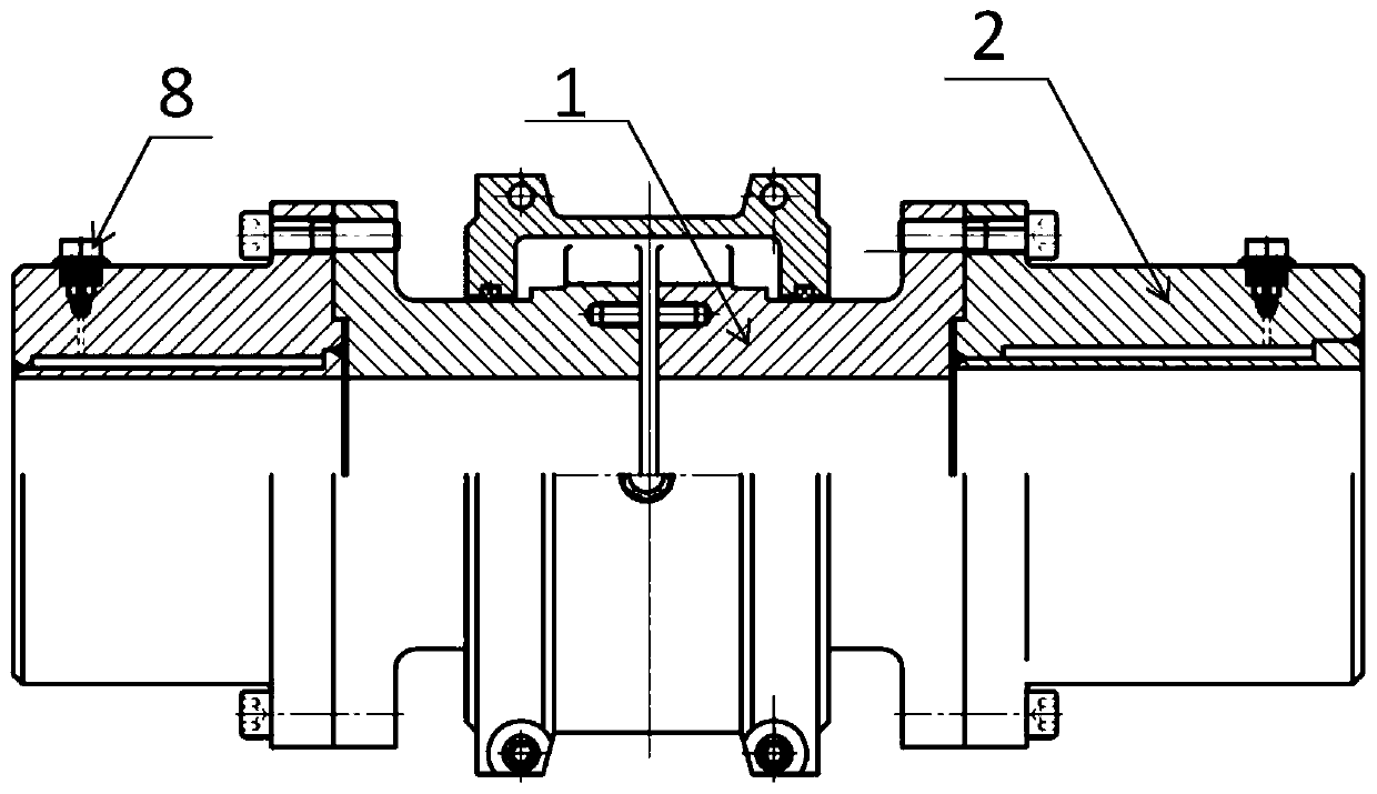
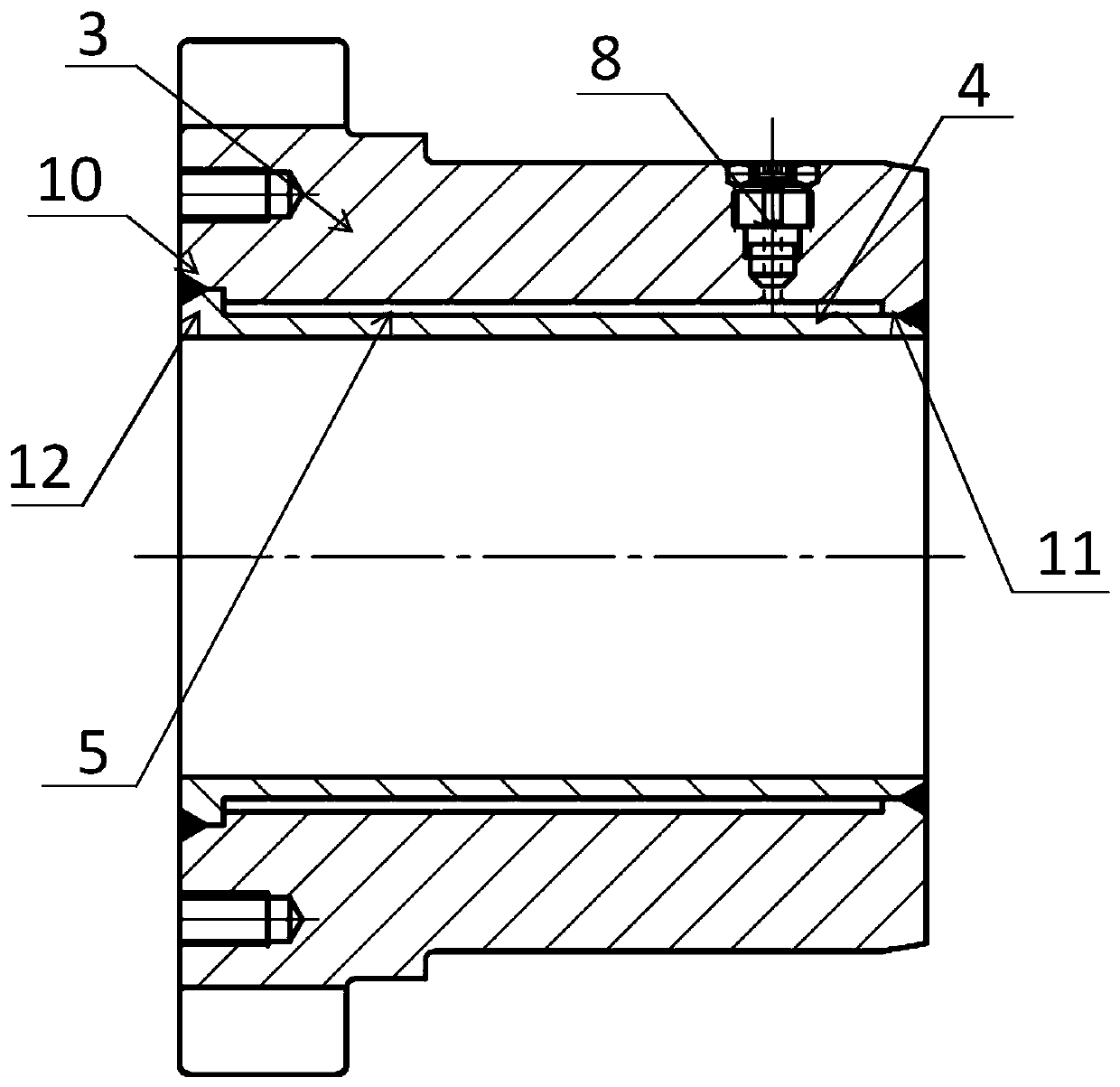
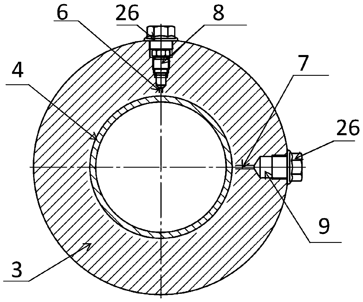
[0034] refer to Figure 1 to Figure 5 As shown, a new type of hydraulic coupling device in this embodiment includes a coupling piece 1 and a coupling sleeve 2 arranged on both sides of the coupling piece 1, and the coupling sleeve 2 includes an outer body 3 connected to the coupling piece 1 and The inner wall pressure sleeve 4 is arranged in the outer casing 3, the inside of the outer casing 3 is hollow, and an annular flange is provided at one end, and a plurality of through-hole teeth are arranged on the annular flange, and the through-hole teeth are used for corresponding connectors The through-hole teeth on 1 are fixedly connected by threaded nuts. The inner hole of the outer casing 3 matches the outer circle of the inner wall pressure sleeve 4. One side of the inner wall of the outer casing 3 is provided with a limit groove 10, and the other The side is provided with an annular projection 11, and the side of the inner wall pressure sleeve 4 in contact with the limit groov...


PUM


Abstract

The invention discloses a novel hydraulic coupling device. According to the technical scheme, the novel hydraulic coupling device comprises a connecting piece and coupling sleeves arranged on the twosides of the connecting piece correspondingly, the coupling sleeves comprise outer sleeve bodies connected to the connecting piece and inner wall pressure sleeves arranged in the outer sleeve bodies,pressure oil cavities are formed between the outer sleeve bodies and the inner wall pressure sleeves, the outer sleeve bodies are provided with oil inlet channels and oil outlet channels which communicate with the pressure oil cavities, and oil inlet nozzles are arranged to be matched with the oil inlet channels, and oil outlet nozzles are arranged to be matched with the oil outlet channels. Theinvention provides a novel power transmission element, the novel power transmission element has the advantages of being compact in structure, light in weight, small in rotational inertia, easy to assemble, safe and reliable, and can be flexibly used in combination with other various elements.

Description

technical field [0001] The invention relates to the technical field of shaft coupling sleeves, more specifically, it relates to a novel hydraulic shaft coupling device. Background technique [0002] Coupling sleeve refers to a device that connects two shafts or shafts and rotating parts, and rotates together during the process of transmitting motion and power, and cannot be disengaged under normal conditions. Sometimes it is also used as a safety device to prevent the connected parts from being subjected to excessive loads and play the role of overload protection. [0003] The traditional connecting device of the coupling sleeve is connected by a key. The coupling sleeve and the shaft are each machined with key grooves, and the coupling sleeve and the shaft are connected by keys. According to the connection requirements, the keys are also divided into various types, and because The existence of the keyway on the shaft not only weakens the strength of the shaft, but also inc...

Claims


Application Information

Patent Timeline
IPC IPC(8): F16D1/04
CPCF16D1/04
Inventor 张代新
Owner 浙江德成机械科技有限公司
Why Eureka
Eureka Blog
Learn More