Method for operating a measuring device and measuring device

A technology for measuring devices and measuring directions, applied in measuring devices, measuring flow/mass flow, fluid velocity measurement, etc., can solve problems such as increasing measurement data evaluation computing power, and achieve the effect of fine structure

Pending Publication Date: 2020-05-29
DIEHL METERING
View PDF1 Cites 2 Cited by
  • Summary
  • Abstract
  • Description
  • Claims
  • Application Information

AI Technical Summary

Problems solved by technology

[0004] The problem in this case is that, especially when the guided waves are conducted over relatively short distances in the pipe wall, the measurement signals of the different modes are generally not possible to be robustly separated, or can on

Method used


Image

  • Method for operating a measuring device and measuring device
  • Method for operating a measuring device and measuring device
  • Method for operating a measuring device and measuring device

Examples


Embodiment Construction

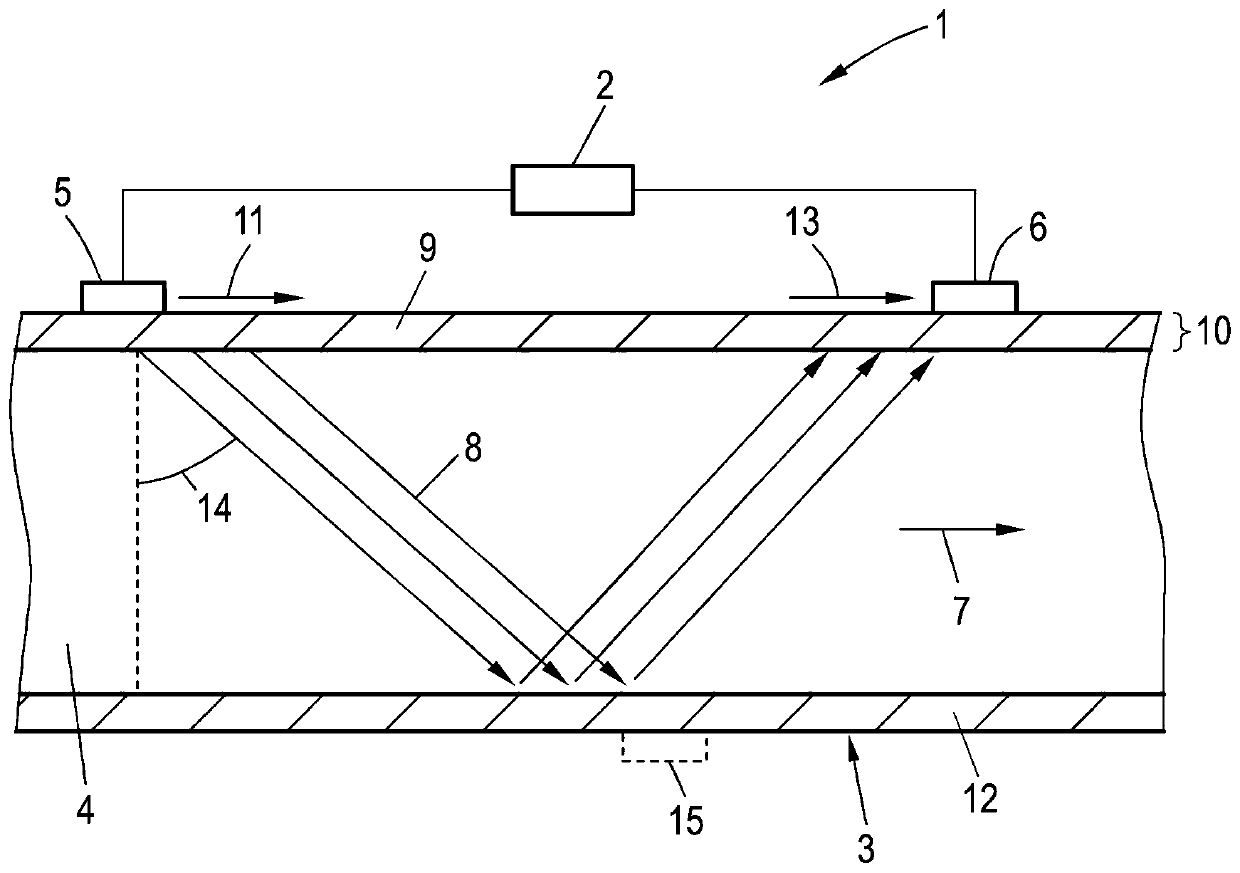
[0038] figure 1Shown is a measuring device 1 for determining a fluid quantity, in particular a flow rate, in relation to a fluid and / or a fluid flow. As will be explained in more detail below, the measuring device 1 is also adapted to determine resulting information about the fluid itself and / or the state of the measuring device 1 . The fluid is conveyed in the direction indicated by the arrow 7 through the interior 4 of the measuring tube 3 . In order to determine the fluid quantity, in particular the flow rate, the time-of-flight from the first oscillating transducer 5 to the second oscillating transducer 6 and from the second oscillating transducer 6 to the first oscillating transducer can be determined by the control device 2 The flight time difference between the flight times of 5. In this case, use is made of the fact that this time-of-flight depends on the velocity component of the fluid parallel to the direction of propagation of the ultrasound beam 8 through the flu...


PUM


Abstract

A method for operating a measuring device is provided. The measuring device has a measurement tube for receiving or conveying a fluid, first and second oscillation transducers on a side wall of the measurement tube, and a control device, wherein the control device drives the first oscillating transducer continuously in chronological order in a first measuring direction for respective mode-selective excitation of a first and a second oscillating mode of waves conducted in the side wall of the measuring tube, and drives the second oscillating transducer continuously in chronological order for respective mode-selective excitation of the first and second oscillating modes of the waves conducted in the side wall of the measuring tube in a second measuring direction. The excited waves are conducted directly in the side wall or indirectly through the fluid and recorded in the other oscillation transducer, resulting in measurement data for each measurement direction and oscillation mode. Result information relates to a property of the fluid or a state of the measuring device determined from the measurement data for both measurement directions and both respective oscillation modes.

Description

technical field [0001] The invention relates to a method for operating a measuring device, in particular a flow meter, comprising a measuring tube for receiving or conveying a fluid, a first oscillating transducer arranged on a corresponding side wall of the measuring tube and the second oscillating transducer, as well as the control device. The invention also relates to a measuring device, in particular a flow meter. Background technique [0002] One possibility for measuring the flow through the measuring tube involves an ultrasonic meter. where at least one ultrasonic transducer is used in order to introduce ultrasonic waves into the fluid flowing through the measuring tube, which are conducted on a straight path or after multiple reflections at walls or special reflective elements to a second ultrasonic transducer . The flow rate through the measuring tube can be determined from the time-of-flight of the ultrasonic waves between the ultrasonic transducers, or from the...

Claims


Application Information

Patent Timeline
IPC IPC(8): G01F1/66G01P5/24
CPCG01F1/662G01P5/245G01F1/66G01F1/667G01N29/024G01N29/222G01N2291/02836
Inventor A·本克特M·梅勒P·普洛斯
Owner DIEHL METERING
Why Eureka
Try Eureka