Battery pole gluing method and battery pole gluing mechanism

A battery and pole technology, which is applied in the field of battery pole gluing method and battery pole gluing mechanism, can solve the problems of low efficiency and poor gluing effect, achieve convenient and reliable positioning, high gluing efficiency, and improve gluing efficiency. sticky effect

Active Publication Date: 2021-05-07
JIANGXI XINWEI POWER ENERGY TECH
View PDF10 Cites 0 Cited by
  • Summary
  • Abstract
  • Description
  • Claims
  • Application Information

AI Technical Summary

Problems solved by technology

[0003] The present invention aims to provide a battery pole gluing method with good gluing effect, which solves the existing problem of poor gluing effect when manually transporting glue into the pole glue tank through a glue gun for gluing
[0004] The present invention also provides a battery pole post gluing mechanism capable of improving the gluing effect and efficiency. The problem of inefficiency

Method used


Image

  • Battery pole gluing method and battery pole gluing mechanism
  • Battery pole gluing method and battery pole gluing mechanism
  • Battery pole gluing method and battery pole gluing mechanism

Examples


Embodiment 2

[0039] Embodiment two, the difference with embodiment one is:

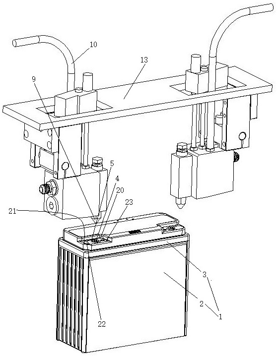
[0040] see Image 6 , one of the two gripping fingers 17 located in front of the conveying direction of the conveyor belt extends beyond the other gripping finger 25 in the direction away from the gripping block. conveyor belt in Image 6 The conveying direction in the Image 6 in the A direction. The clamping finger driving cylinder is a double-stroke cylinder. When the clamp finger drives the cylinder to extend a stroke, the clamp finger located in front of the conveying direction of the conveyor belt blocks the battery 1 on the conveyor belt from moving forward.

[0041] The process of positioning the battery in this embodiment is as follows: in the initial state, the clamping block driving cylinder is in a state of outputting one stroke, and when the battery is in contact with the clamping fingers 24 located in front of the conveyor belt in the conveying direction, the clamping block driving cylinder Exte...

Embodiment 3

[0042] The third embodiment is that the following changes have been made on the basis of the first embodiment and the second embodiment:

[0043] see Figure 7 , Figure 8 and Figure 9 , The frame is equipped with a flat glue mechanism for leveling the glue in the two pole glue grooves one by one. The gluing mechanism is located between the leveling gluing mechanism and the heating mechanism.

[0044] The leveling glue mechanism includes a horizontal chute 41 , a vertical pipe 26 , a cover plate translation mechanism 27 and a cover plate vertical movement mechanism 28 .

[0045] One end of the horizontal chute is provided with a cover plate outlet hole 29 . Two supporting pieces 30 which are opened downward are hinged on the lower side of the outlet hole of the cover plate. The opening area of ​​the outlet hole of the cover plate is equal to the area of ​​the flat cover plate 31 . The flat cover plate can just pass through the pole glue groove 5 to cover the pole glue g...


PUM


Abstract

The invention relates to a method for gluing battery poles. After the poles are preheated to a set temperature, hot melt adhesive is delivered to the pole glue tank. The pole moves so that the hot-melt glue surrounds the pole; the hot-melt glue cools and solidifies to seal the pole and the middle cover; it also relates to a battery pole gluing mechanism, including a conveyor belt, a preheating device and a gluing The preheating device is equipped with two heating heads, the dispensing device is equipped with two glue nozzles, and the frame is also equipped with a positioning that keeps the battery at a position where the two poles can be heated by the two heating heads. Clamp and another positioning clamp to hold the battery in a position where the two glue nozzles can output hot melt glue into the two pole glue grooves. The invention has the advantage of good gluing effect, and solves the existing problem of poor gluing effect when the glue is manually transported into the pole glue tank through a glue gun for gluing.

Description

technical field [0001] The invention relates to the technical field of battery production, in particular to a battery pole gluing method and a battery pole gluing mechanism. Background technique [0002] The basic structure of a lead-acid battery includes a battery body and a middle cover arranged on the battery itself. The battery body is provided with two poles, and the middle cover is provided with two pole glue grooves. The bottom walls of the two pole glue grooves protrude from the middle cover. In the production process of lead-acid batteries, the battery poles and the middle cover are usually connected by glue sealing. The existing method of gluing into the pole glue tank is done manually through a glue gun, and the existing gluing method has the shortcomings of low efficiency and the glue cannot reliably glue the middle cover and the pole together. SUMMARY OF THE INVENTION [0003] The invention aims to provide a battery pole gluing method with good gluing effect...

Claims


Application Information

Patent Timeline
Patent Type & Authority Patents(China)
IPC IPC(8): H01M10/12B05C5/00B05C5/02B05C9/14B05C13/02
CPCB05C5/001B05C5/0208B05C9/14B05C13/02H01M10/12Y02E60/10Y02P70/50
Inventor 张森薛海东丁祯刚
Owner JIANGXI XINWEI POWER ENERGY TECH
Why Eureka
Try Eureka