Heat exchanger

A technology of heat exchangers and heat exchange parts, applied in heat exchange equipment, indirect heat exchangers, heat exchanger shells, etc., can solve problems such as abnormal sound, insufficient subcooling degree, and insufficient refrigerant supercooling degree

Active Publication Date: 2020-05-29
DENSO CORP
View PDF9 Cites 0 Cited by
  • Summary
  • Abstract
  • Description
  • Claims
  • Application Information

AI Technical Summary

Problems solved by technology

As the first technical problem during cooling, when a refrigerant adjustment unit is provided that is integrated with a liquid receiver that stores liquid refrigerant, and switches the flow of refrigerant during cooling operation and heating operation, due to The high-temperature and high-pressure gas-phase refrigerant that flows into the refrigerant adjustment unit has the following technical problem: the refrigerant flowing in the heat exchanger is heated and the degree of supercooling is insufficient, thereby reducing the cooling performance
As the second technical problem in refrigeration, there is a technical problem that the gas-phase refrigerant is mixed into the refrigerant flowing into the expansion valve due to insufficient supercooling degree, and abnormal sound is generated.

Method used


Image

  • Heat exchanger
  • Heat exchanger
  • Heat exchanger

Examples


Embodiment Construction

[0023] Hereinafter, this embodiment will be described with reference to the drawings. In order to facilitate understanding and description, the same components are given the same reference numerals as much as possible in each drawing, and overlapping descriptions are omitted.

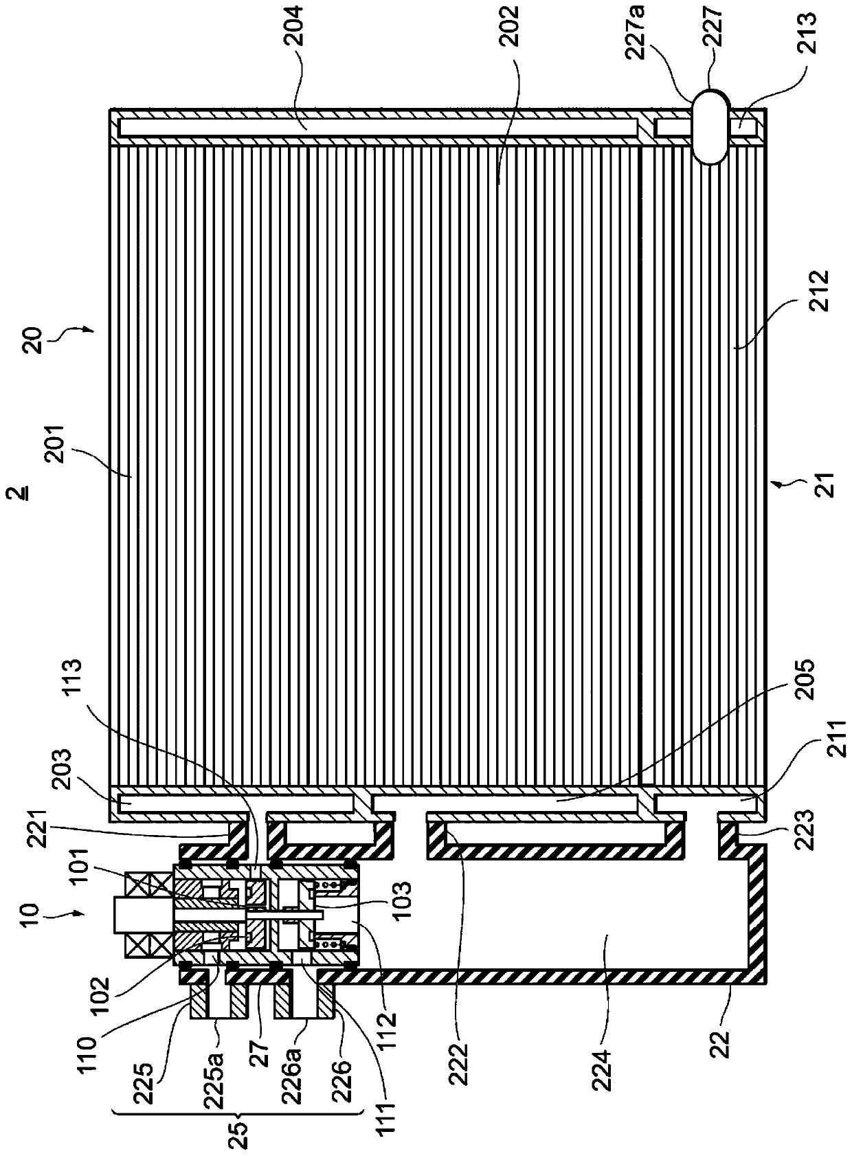
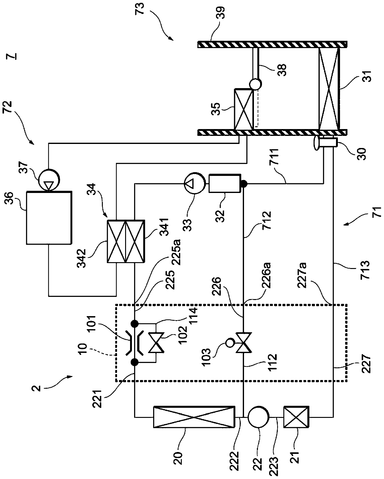
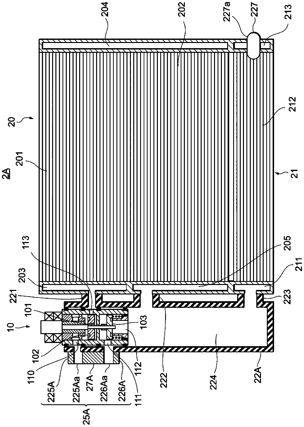
[0024] like figure 1 As shown, the heat exchanger 2 of the present embodiment includes an upstream heat exchange unit 20 , a downstream heat exchange unit 21 , and an accumulator 22 . The upstream side heat exchange unit 20 has two upstream side cores 201 , 202 and header tanks 203 , 204 , 205 . In the present embodiment, a configuration having two upstream cores 201 and 202 was shown as an example, but the number of cores may be one or three or more. The upstream side cores 201, 202 are parts for heat exchange between the refrigerant flowing inside and the air flowing outside, and have tubes through which the refrigerant passes and fins provided between the tubes. .

[0025] A header tank 203 is at...


PUM


Abstract

A heat exchanger is provided with: an inflow port (225a), through which a refrigerant flows in; a cooling flow outlet port (227a), through which the refrigerant flows out when cooling operations are performed; and a warming flow outlet port (226a), through which the refrigerant flows out when warming operations are performed. The ports are disposed such that the distance between the inflow port (225a) and the warming flow outlet port (226a) is shorter than the distance between the inflow port (225a) and the cooling flow outlet port (227a).

Description

[0001] Cross-references to related applications [0002] This application is based on Japanese Patent Application No. 2017-197822 for which it applied on October 11, 2017, the priority is claimed, and the whole content of this patent application is incorporated in this specification by reference. technical field [0003] The invention relates to a heat exchanger used in a heat pump system for cooling and heating. Background technique [0004] A heat exchanger described in Patent Document 1 below is known as a heat exchanger used in a heat pump system that performs a cooling operation and a heating operation. In the heat exchanger described in Patent Document 1 below, during cooling, a high-temperature and high-pressure gas-phase refrigerant flows into the condensing heat exchange portion, is cooled, and becomes a gas-liquid two-phase refrigerant, which flows into the liquid receiving portion. The liquid-phase refrigerant saturated with the gas-liquid two-phase refrigerant f...

Claims


Application Information

Patent Timeline
Patent Type & Authority Applications(China)
IPC IPC(8): F25B41/04B60H1/32F25B5/04F25B6/04F25B39/00F25B39/02F25B39/04
CPCB60H1/32F25B6/04F25B39/02F25B39/04F25B2400/0417F25B2400/0411F25B2400/0409F25B2600/2501F25B2500/18F28D1/05375F28F9/0253F25B29/003F28F13/06
Inventor 杉村辽平川久保昌章加藤大辉伊藤哲也三枝弘
Owner DENSO CORP
Why Eureka
Try Eureka