Polyurethane mattress with internal airflow adjusting function

A technology of airflow adjustment and polyurethane, which is applied in the field of mattresses to achieve the effect of increasing practicability

Active Publication Date: 2020-06-02
GLORY HOME FURNISHING JIAXING
View PDF7 Cites 0 Cited by
  • Summary
  • Abstract
  • Description
  • Claims
  • Application Information

AI Technical Summary

Problems solved by technology

[0004] Aiming at the deficiencies of the prior art, the present invention provides a polyurethane mattress with internal airflow adjustment, which has the advantages of allowing the mattress to recover faster and solves the above-mentioned problems

Method used


Image

  • Polyurethane mattress with internal airflow adjusting function
  • Polyurethane mattress with internal airflow adjusting function
  • Polyurethane mattress with internal airflow adjusting function

Examples


Embodiment 1

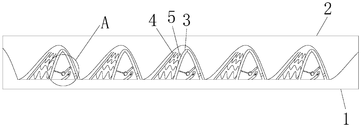
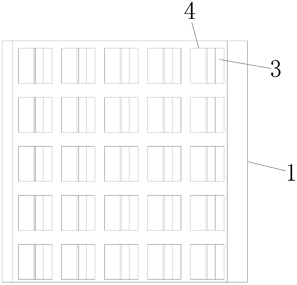
[0027] Example 1: Please refer to figure 1 and image 3 , a polyurethane mattress with internal airflow adjustment, comprising a lower plate 1 and an upper plate 2, the lower plate 1 is a polyurethane material plate with raised left and right ends, and the upper plate 2 is a polyurethane plate with a corrugated lower surface, so The upper surface of the lower plate 1 is provided with an extrusion circulation device 3, and a spring 5 is arranged on the side wall of the extrusion circulation device 3, and one end of the spring 5 is fixedly connected with the side wall of the extrusion circulation device 3, and the other end of the spring 5 is provided with an extrusion plate 4. The extrusion plate 4 is arranged obliquely along the wave inclination direction of the upper plate 2, and the spring 5 is fixedly connected to the extrusion plate 4. The number of the extrusion circulation devices 3 is 100 to 20 on the upper plate, and the extrusion circulation devices 3 is smaller than...

Embodiment 2

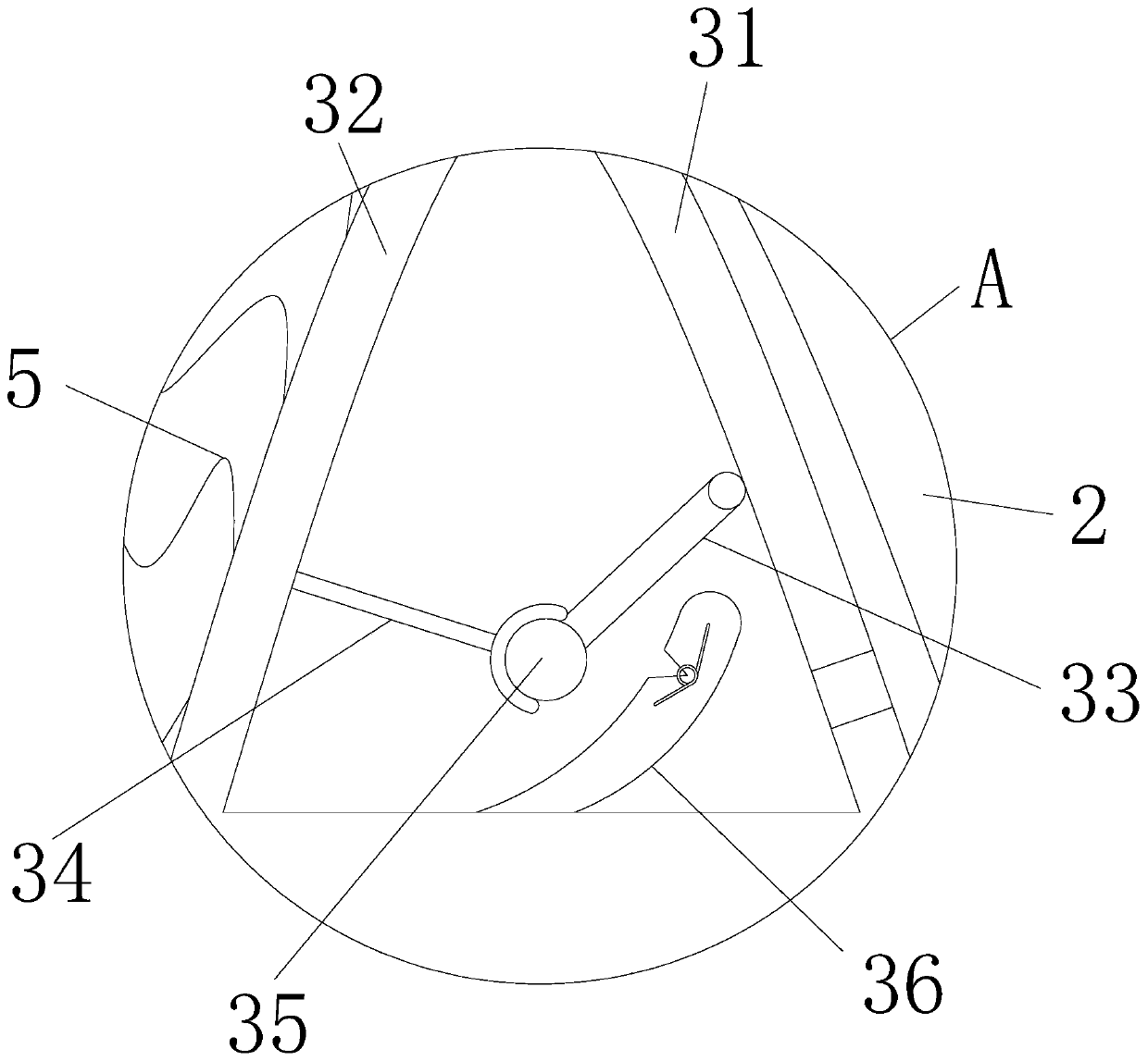
[0028] Embodiment 2: On the basis of Embodiment 1, please refer to figure 2 , the extrusion flow device 3 includes a fixed plate 31 and an elastic movable plate 32, fixedly connected between the fixed plate 31 and the elastic movable plate 32, and the spring 5 is arranged on the wall surface of the elastic movable plate 32 side, and the fixed plate 31 side An air outlet is opened through the wall, and the air outlet position on the fixed plate 31 is located at the bottom end of the side wall of the fixed plate 31, and a connecting rod 33 is arranged on the side wall of the fixed plate 31 near the elastic movable plate 32, and the connecting rod 33 It is installed on the side wall of the fixed plate 31 through the hinge, and the elastic movable plate 32 is provided with a catcher 34 on the side wall near the fixed plate 31. The catcher 34 is a combination, and specifically the catcher 34 consists of a mounting rod. It is composed of a semi-cylindrical shovel, and the mounting ...

Embodiment 3

[0029] Embodiment three: on the basis of embodiment two, please refer to figure 2 , the part of the upper surface of the lower plate 1 located in the extrusion flow device 3 is provided with a rebound arc plate 36, the front and rear length of the rebound arc plate 36 is the same as that of the clamping shaft 35, and the rebound arc plate 36 is fixedly installed on the lower On the upper surface of the board 1 , a torsion spring is arranged in the rebound arc plate 36 , and the rebound arc plate 36 is inclined to the direction of the connecting rod 33 , and the horizontal position of the uppermost end of the rebound arc plate 36 is higher than the clamping shaft 35 .

[0030]When in use, the user is located above the upper plate 2. At this time, the upper plate 2 will be squeezed, and the squeezed plate 4 at the squeezed position will also be squeezed synchronously. The kinetic energy transmission of the spring 5 will drive the extrusion flow. When the device 3 is squeezed sy...


PUM


Abstract

The invention relates to the technical field of mattresses, and discloses a polyurethane mattress with an internal air flow adjusting function. The device comprises a lower plate and an upper plate, wherein the lower plate is a polyurethane material plate with bulges at the left end and the right end; the upper plate is a polyurethane plate with a wavy lower surface; extrusion circulating devicesare arranged on the upper surface of the lower plate; springs are arranged on the side walls of the extrusion circulating devices; one ends of the springs are fixedly connected with the sidewalls of the extrusion circulating devices; extrusion plates are arranged at the other ends of the springs; and the extrusion plates are obliquely arranged along the wave inclination direction of the upper plate. According to the polyurethane mattress with the internal airflow adjusting function, the extrusion circulating devices, the extrusion plates and the spring are arranged for matched movement, so theelastic movable plate is arranged on the fixing plate, so elastic movable plates can deform, and air flow is thus generated in the extrusion circulating devices; and the air flow generated in the extrusion circulating devices can flow out from air outlets formed in fixed plates, so the mattress can be restored more quickly during shape restoration, and the practicability of the mattress is improved.

Description

technical field [0001] The invention relates to the technical field of mattresses, in particular to a polyurethane mattress with internal airflow adjustment. Background technique [0002] In daily life, people spend about half of their time in sleep. Mattress is one of the important bedding. With the progress of life, mattresses gradually have various types, including spring mattress, polyurethane Various mattresses such as mattresses, wherein the polyurethane mattress can carry out shape memory deformation because of its special material, thereby can allow the user to sleep more comfortably, a kind of polyurethane sponge mattress proposed at present (public number : CN204306469U) the utility model discloses a polyurethane sponge mattress, which comprises the first sponge body, the second sponge body, the third sponge body and the fourth sponge body successively stacked from bottom to top all made of polyurethane sponge, The upper surface of the third sponge body is an embo...

Claims


Application Information

Patent Timeline
Patent Type & Authority Applications(China)
IPC IPC(8): A47C27/045
CPCA47C27/045
Inventor 丘国豪丘国良国海玲刘友川邓宣晖
Owner GLORY HOME FURNISHING JIAXING
Why Eureka
Try Eureka