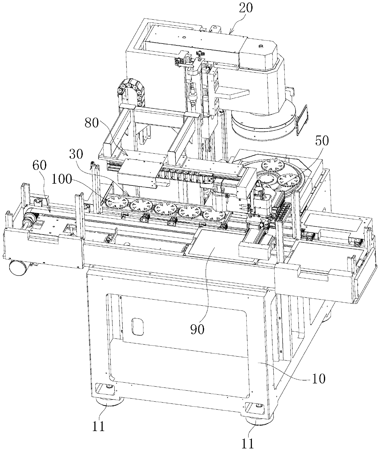
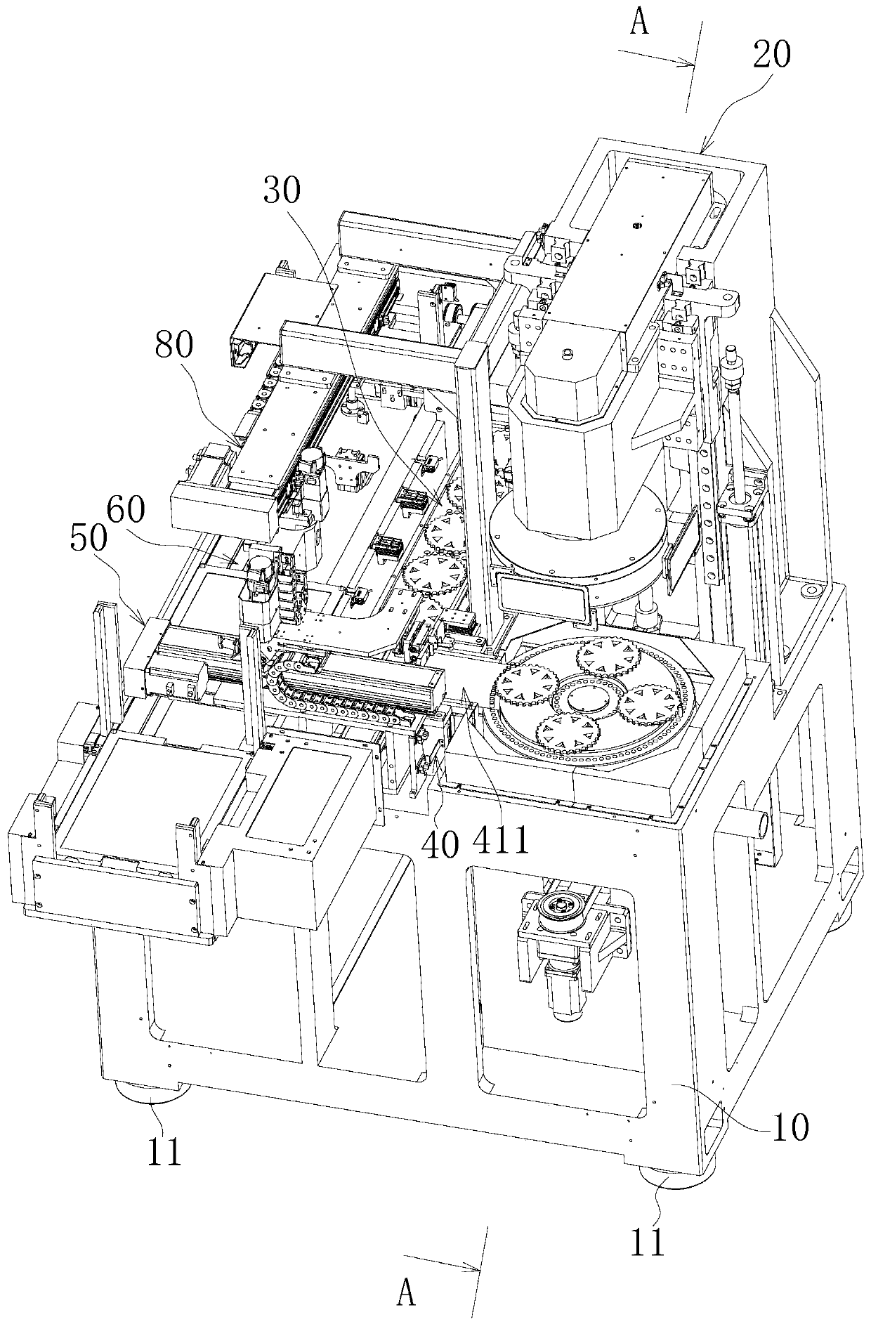
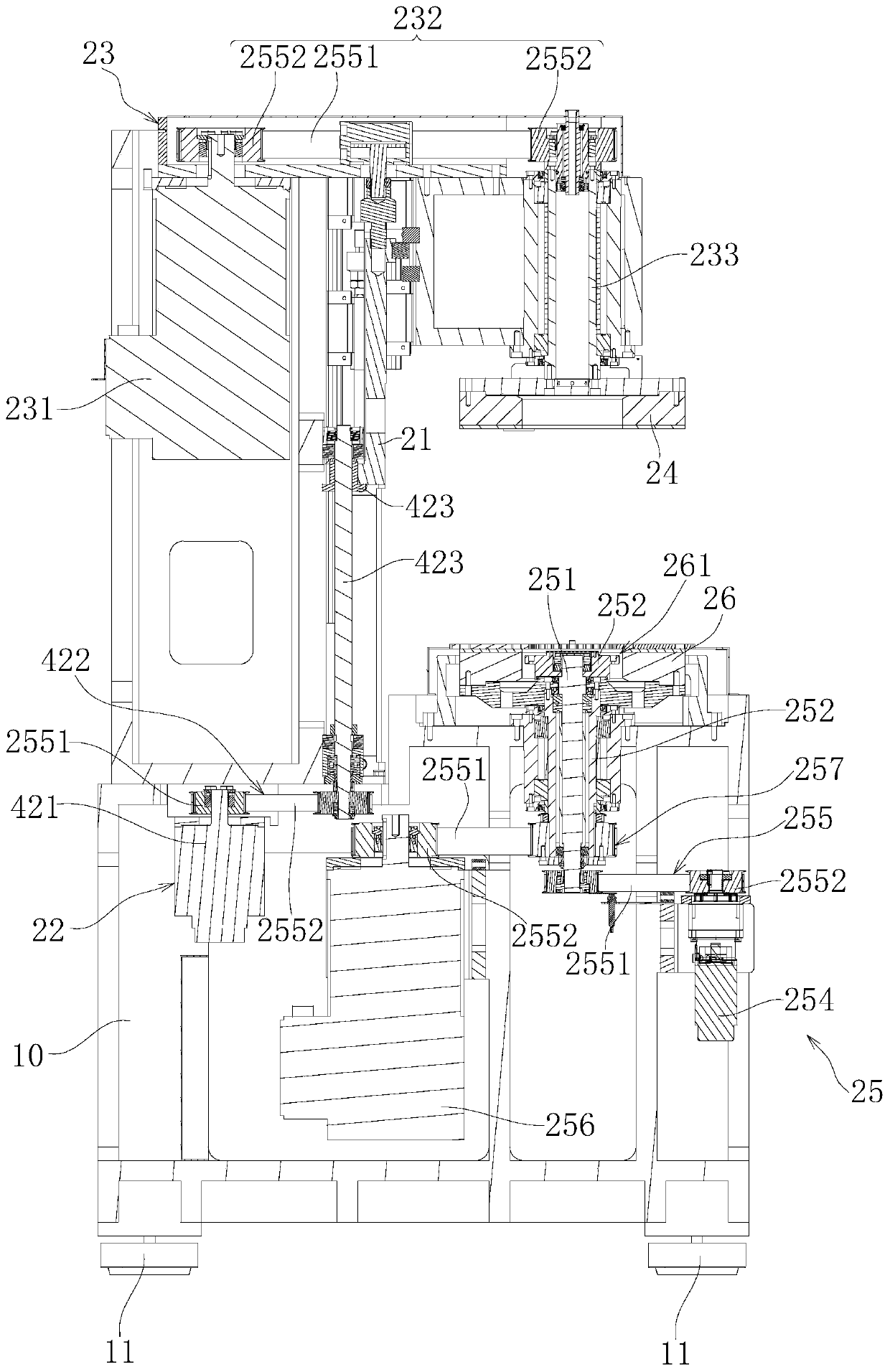
Cutter grinding machine

A tool grinding machine and cutting tool technology, applied in the direction of grinding machine, grinding bed, grinding machine parts, etc., can solve problems such as low processing efficiency and accuracy impact, and achieve the effect of improving production efficiency and good accuracy

Active Publication Date: 2020-06-02
SHENZHEN SHENLAN PRECISION MACHINERY
View PDF7 Cites 4 Cited by
  • Summary
  • Abstract
  • Description
  • Claims
  • Application Information

AI Technical Summary

Problems solved by technology

[0003] The object of the present invention is to provide a tool grinding machine, aiming at solving the problem that the tool grinding machine in the prior art has a low processing efficiency caused by manual loading, and at the same time, the accuracy of fixture insertion is not possible, which seriously affects the tool grinding. Technical issues of processing pass rate

Method used


Image

  • Cutter grinding machine
  • Cutter grinding machine
  • Cutter grinding machine

Examples


Embodiment Construction

[0058] Embodiments of the present invention are described in detail below, examples of which are shown in the drawings, wherein the same or similar reference numerals designate the same or similar elements or elements having the same or similar functions throughout. Attached below by reference Figure 1-10 The described embodiments are exemplary and are intended to explain the present invention, but should not be construed as limiting the present invention.

[0059] In describing the present invention, it should be understood that the terms "length", "width", "upper", "lower", "front", "rear", "left", "right", "vertical", The orientation or positional relationship indicated by "horizontal", "top", "bottom", "inner", "outer", etc. are based on the orientation or positional relationship shown in the drawings, and are only for the convenience of describing the present invention and simplifying the description, rather than Nothing indicating or implying that a referenced device o...


PUM


Abstract

The invention belongs to the technical field of cutter machining, and particularly relates to a cutter grinding machine. The cutter grinding machine comprises a rack and a grinding mechanism, a fixture bearing mechanism, a fixture channel and a fixture mechanical hand. The fixture bearing mechanism comprises a bearing plate and a linear motion assembly. The linear motion assembly is installed on the rack. The driving end of the linear motion assembly is connected with the bearing plate and used for driving the bearing plate to move in the length direction of the bearing plate. A plurality of positioning regions evenly arranged in the length direction of the bearing plate and used for bearing a fixture are arranged on the bearing plate. An opening for allowing the fixture to move in or moveout is formed in the side, close to the grinding mechanism, of each positioning region. The fixture channel is arranged between the grinding mechanism and the fixture bearing mechanism and used for communicating the opening with the grinding mechanism. The fixture mechanical hand drags the fixture so as to feed the fixture inside the fixture bearing mechanism into the grinding mechanism and feedthe fixture inside the grinding mechanism into the fixture bearing mechanism, and therefore automatic fixture feeding and discharging are achieved.

Description

technical field [0001] The invention belongs to the technical field of tool processing, and in particular relates to a tool grinding machine. Background technique [0002] In the production process of the tool, it is necessary to use the tool grinder to grind the surface of the tool to eliminate microscopic defects such as burrs on the tool surface. At present, the tool grinding machine generally places the tool in the jig, and then puts the jig It is sent into the grinding mechanism together with the tool for grinding processing, but in the actual processing process, the fixture is generally put into the grinding mechanism manually, on the one hand, resulting in low efficiency of tool grinding; on the other hand, The accuracy of the position of the jig placed by the personnel on the grinding mechanism is poor, which seriously affects the pass rate of the grinding process of the tool. Contents of the invention [0003] The object of the present invention is to provide a t...

Claims


Application Information

Patent Timeline
IPC IPC(8): B24B9/04B24B41/00B24B41/02B24B41/06B24B51/00
CPCB24B9/04B24B41/005B24B41/02B24B41/06B24B51/00
Inventor 郑青焕
Owner SHENZHEN SHENLAN PRECISION MACHINERY
Why Eureka
Try Eureka