Fuel injection system with self-protection function and pressure control method

A fuel injection system and fuel injector technology, which is applied to fuel injection pumps, fuel injection devices, charging systems, etc., can solve the problems of high pressure control valves, low effective utilization of high pressure fuel, and high material and manufacturing requirements.

Active Publication Date: 2020-06-02
FAW JIEFANG AUTOMOTIVE CO
View PDF7 Cites 0 Cited by
  • Summary
  • Abstract
  • Description
  • Claims
  • Application Information

AI Technical Summary

Problems solved by technology

[0004] 1) Ineffective release of high-pressure fuel increases system high-pressure energy loss;
[0005] 2) The effective utilization rate of high-pressure fuel is reduced, which increases the fuel supply load of the high-pressure fuel pump;
[0006] 3) The fluid cavitation problem caused by high-pressure oil leakage reduces the reliability of high-pressure control valves and systems
[0007] 4) The high-pressure control valve withstands high pressure, even above 200MPa, which requires high material and manufacturing requirements and high cost
[0008] 5) No self-protection function
[0010] Although the existing technology can improve the steady-state pressure regulation characteristics and responsiveness of the fuel injection system, because the high-pressure control valve is set in the high-pressure area downstream of the high-pressure fuel pump, it will inevitably produce ineffective release of high-pressure fuel during work, making the high-pressure fuel effective. The utilization rate is reduced, the high-pressure energy loss of the system is large, and the fuel supply load of the fuel pump is increased. At the same time, the high-pressure control valve withstands extremely high pressure, even up to 200MPa, which requires high material and manufacturing requirements and high cost. Fluid cavitation problems caused by this can reduce the reliability of high-pressure control valves and systems

Method used


Image

  • Fuel injection system with self-protection function and pressure control method
  • Fuel injection system with self-protection function and pressure control method
  • Fuel injection system with self-protection function and pressure control method

Examples


Embodiment Construction

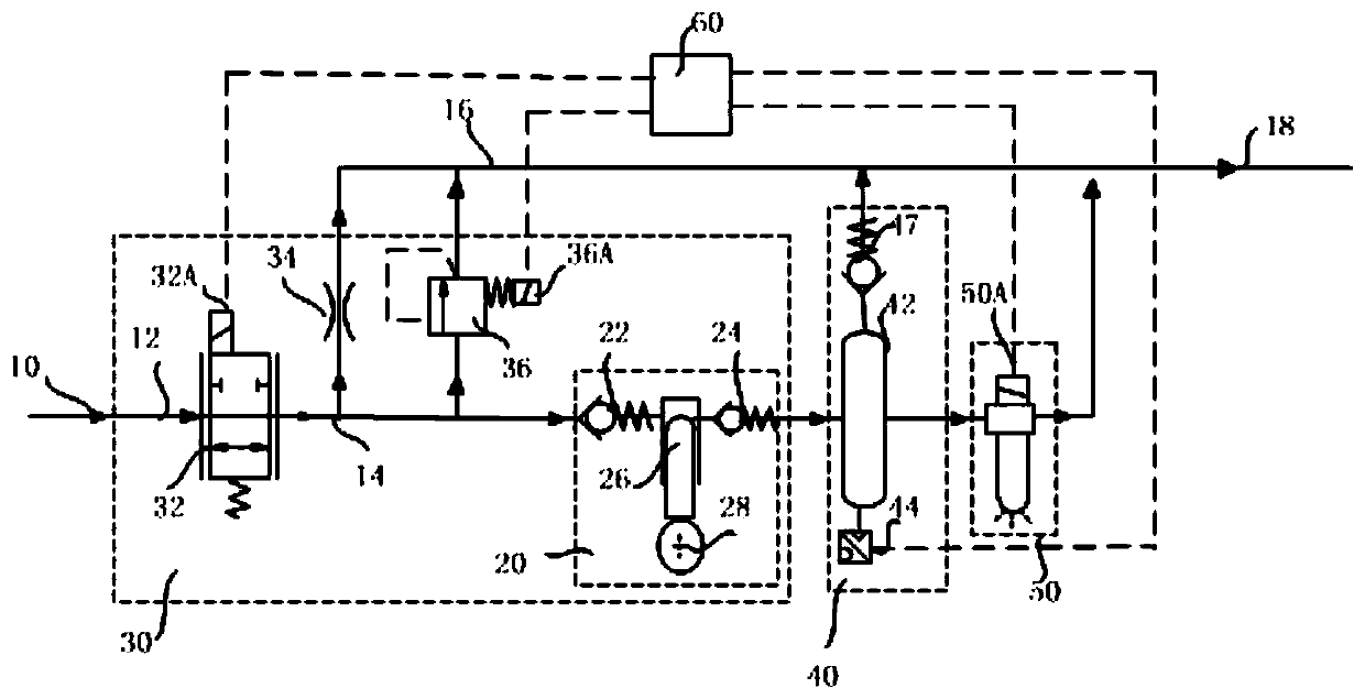
[0038] refer to figure 1 , a fuel injection system with self-protection function, suitable for commercial vehicle power, various construction machinery power, and more suitable for ship power.

[0039] A fuel supply 10 is distributed to the first supply conduit 12 by a low pressure fuel pump, and a flow control valve 32 is provided to meter fuel into the second supply conduit 14 upstream of at least one high pressure fuel pump 20 . An embodiment of the high pressure fuel pump 20 design includes at least an inlet check valve 22 , an outlet check valve 24 , a plunger couple 26 , a drive mechanism 28 and other auxiliary components. The other auxiliary components include the base of the pump body, which is used to arrange various control valves, pipelines, check valves, plug couples, and driving mechanisms. The driving structure 28 is to ensure that the plunger of the plunger pair realizes reciprocating motion as required. The high-pressure common rail assembly 40 stores the out...


PUM


Abstract

The invention belongs to the technical field of engines, and specifically relates to a fuel injection system with a self-protection function and a pressure control method. The fuel injection system comprises a high-pressure fuel pump, a high-pressure common rail assembly and a fuel injector; the high-pressure fuel pump, a high-pressure common rail and the fuel injector are sequentially connected through a pipeline; and a low-pressure control valve, a drainage hole and a flow control valve are sequentially arranged on the upper stream of the high-pressure fuel pump. According to the fuel injection system with the self-protection function and the pressure control method, the flow control valve works in cooperation with the low-pressure control valve to realize self-protected fuel metering and pressure adjustment functions, so that the fuel injection system has better pressure regulation characteristics in the dynamic process.

Description

technical field [0001] The invention belongs to the technical field of engines, and specifically relates to a fuel injection system and a pressure control method with self-protection functions. Background technique [0002] An engine electronically controlled high pressure fuel injection system typically includes at least one high pressure fuel pump, a high pressure common rail, several fuel injectors and an electronic control unit. In a schematic design, the fuel injectors will be supplied with high pressure fuel by one or more high pressure fuel pumps connected to a high pressure common rail, where the fuel high pressure pumps pressurize the fuel and the common rail distributes the pressurized fuel to each fuel injection The electronic control unit provides control signals according to the requirements of the engine's working conditions, so as to ensure that the high-pressure fuel injection system can provide high-pressure fuel for the engine at regular intervals and quant...

Claims


Application Information

Patent Timeline
IPC IPC(8): F02M45/00F02M59/44F02M59/46F02M65/00
CPCF02M45/00F02M59/44F02M59/466F02M65/00F02M65/003
Inventor 吴永煌金昱森李振强顾浩
Owner FAW JIEFANG AUTOMOTIVE CO
Why Eureka
Try Eureka