Near-eye display device

A near-eye display and display panel technology, applied in optical components, optics, instruments, etc., can solve problems such as high equipment requirements, high manufacturing process difficulty, difficult yield control, etc., and achieve the effect of reducing segmentation and improving display quality

Active Publication Date: 2020-06-02
AU OPTRONICS CORP
View PDF27 Cites 1 Cited by
  • Summary
  • Abstract
  • Description
  • Claims
  • Application Information

AI Technical Summary

Problems solved by technology

However, smaller pixels must be matched with higher-precision manufacturing technology, such as high-precision photolithography manufacturing technology, which makes the manufacturing process more difficult, the yield rate is difficult to control, and the equipment requirements are relatively high, and the manufacturing cost also decreases. surge

Method used


Image

  • Near-eye display device
  • Near-eye display device
  • Near-eye display device

Examples


Embodiment Construction

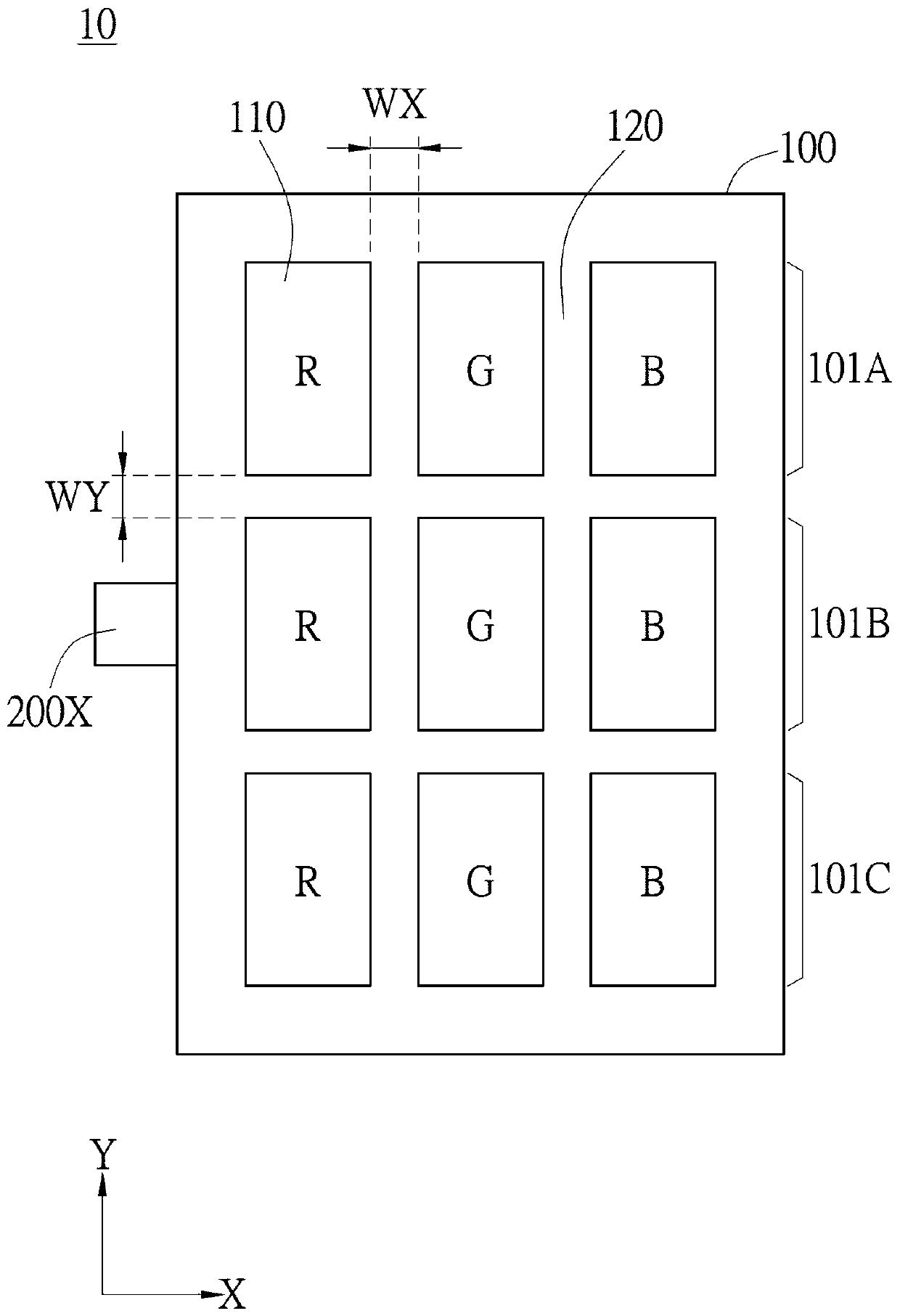
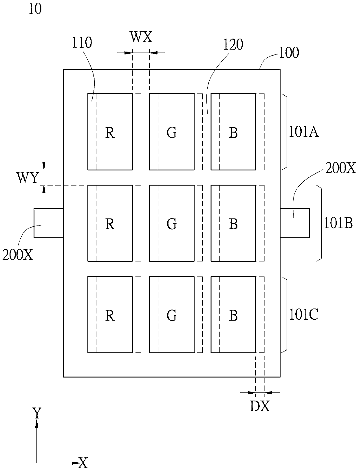
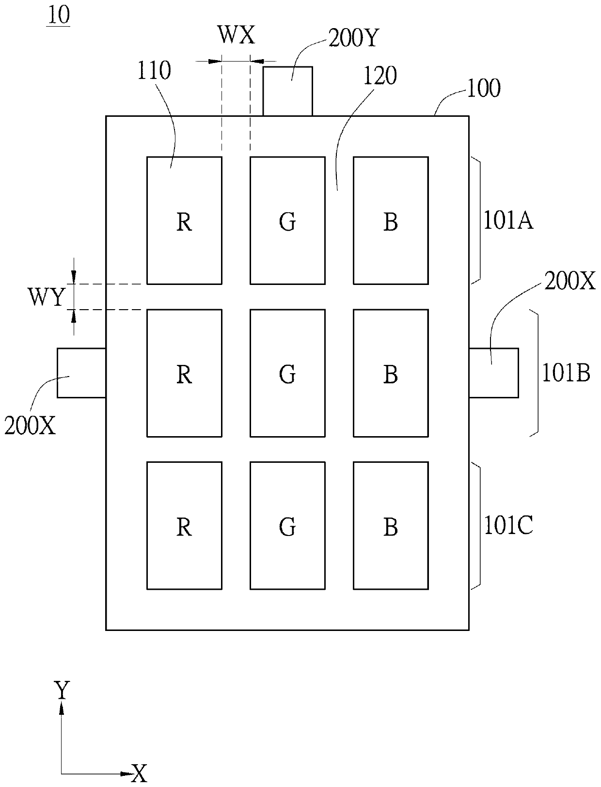
[0035] In the drawings, the thickness of layers, films, panels, regions, etc., are exaggerated for clarity. Throughout the specification, the same reference numerals denote the same elements. It will be understood that when an element such as a layer, film, region, or substrate is referred to as being "on" or "connected to" another element, it can be directly on or connected to the other element, or Intermediate elements may also be present. In contrast, when an element is referred to as being "directly on" or "directly connected to" another element, there are no intervening elements present. As used herein, "connected" may refer to a physical and / or electrical connection. Furthermore, when being "electrically connected" or "coupled", other elements may exist between two elements.

[0036] It should be understood that although the terms "first", "second", "third" etc. may be used herein to describe various elements, components, regions, layers and / or sections, these element...


PUM


Abstract

The invention discloses a near-eye display device, which includes a display panel and a vibrating element, wherein the display panel includes a plurality of pixels; the vibrating element is disposed on the side of the display panel, and the vibrating element vibrates to drive the display panel to vibrate, causing multiple pixels to reciprocate and displace, wherein the vibration amplitude of the vibration element is less than 100 [mu]m.

Description

technical field [0001] The invention relates to a near-eye display device, in particular to a near-eye display device which reduces the screen door effect. Background technique [0002] In display devices, display clarity is usually evaluated by whether pixels can be seen visually. When the pixel density is insufficient, visually you will see a dividing line between the pixels, just like looking at things behind a screen window, which is called the "screen-door effect (screen-door effect)". Generally speaking, when the viewing distance between the display device and the user is larger, the number of pixels that the user can see at a fixed viewing angle is larger, making the screen door effect less distinct. However, in the application of near-eye display devices such as virtual reality, the display device is placed almost close to the user's eyes, so that the viewing distance is only a few centimeters, resulting in a significant increase in the number of pixels that can be ...

Claims


Application Information

Patent Timeline
Patent Type & Authority Applications(China)
IPC IPC(8): G02B27/01
CPCG02B27/0176
Inventor 林国栋陈宪泓
Owner AU OPTRONICS CORP
Why Eureka
Try Eureka