Supercharge Your Innovation With Domain-Expert AI Agents!

LED dispensing method

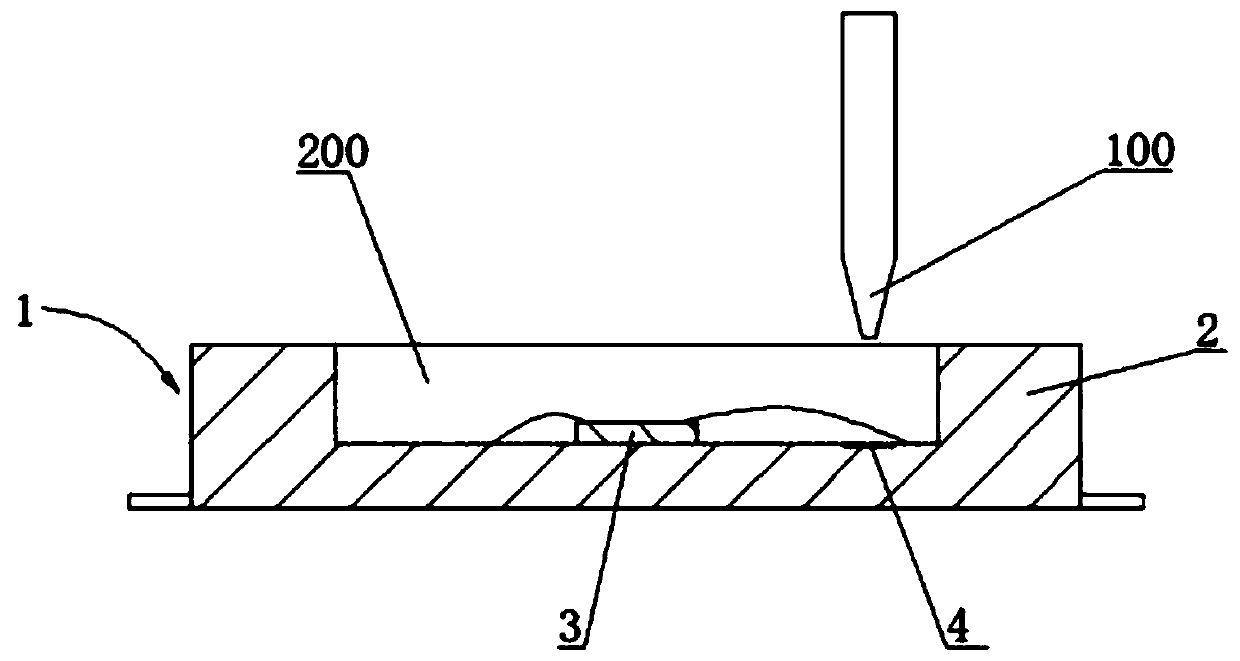
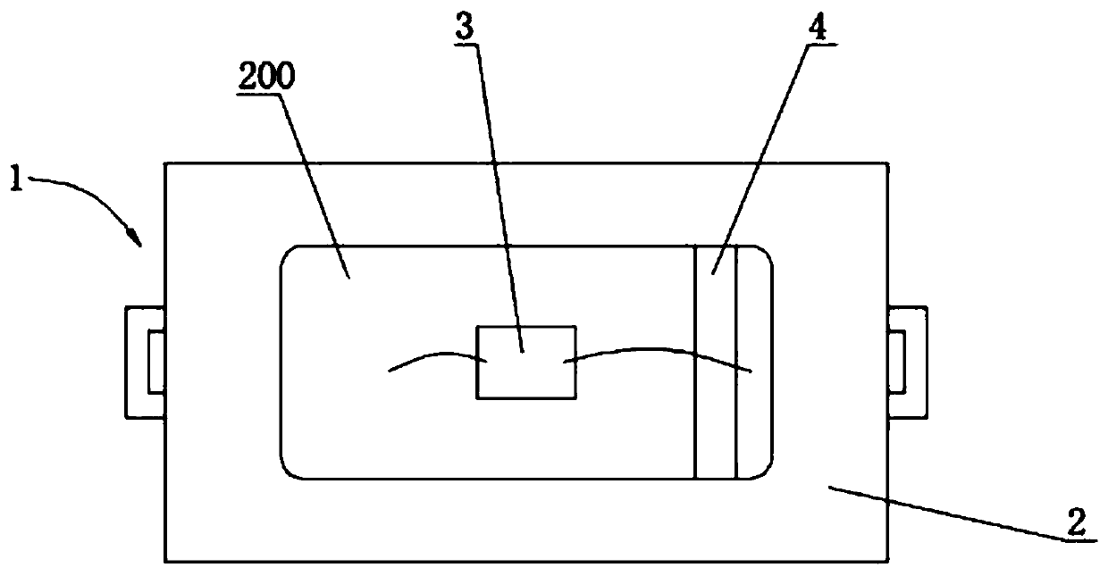
A technology of LED encapsulation and dispensing, which is applied in the direction of electrical components, circuits, semiconductor devices, etc. It can solve the problems that the encapsulation glue cannot flow evenly, the suction nozzle cannot hold the bracket, and affect the appearance of the LED, so as to improve the light extraction efficiency and prevent overflow. Glue, evenly distributed effect

Inactive Publication Date: 2020-06-02
贵州景弘光电有限公司
View PDF0 Cites 0 Cited by
  • Summary
  • Abstract
  • Description
  • Claims
  • Application Information

AI Technical Summary

Problems solved by technology

This kind of glue is aligned on the top of the LED chip. Since the slot inside the PPA bracket bowl is lower than the position of the silver plating layer, if the glue is dispensed from a non-slot position, the packaging glue will not flow evenly and appear due to the existence of uneven positions. Glue overflow phenomenon
In order to solve the above problems, a new dispensing method has emerged, that is, the dispensing head with encapsulation glue is vertically lowered and aligned with the position near the fishing groove in the plastic bracket of the LED chip, and then the glue is controlled, then the dispensing head is raised, and finally moved The dispensing head goes to the position of another LED chip for dispensing operation, but since the dispensing position is close to the position of the plastic bracket, and one-time glue is released at this position, after the glue is discharged, the packaging glue is combined with the side close to the plastic bracket Glue overflow and glue phenomenon will affect the appearance of LED, and glue overflow and glue will cause the problem that the suction nozzle cannot hold the bracket during the subsequent moving of the bracket, reducing production efficiency

Method used


Image

  • LED dispensing method
  • LED dispensing method

Examples


Embodiment 1

[0017] In order to make the object, technical solution and advantages of the present invention clearer, the present invention will be further described in detail below in conjunction with the accompanying drawings and embodiments. It should be understood that the specific embodiments described here are only used to explain the present invention, not to limit the present invention.

[0018] This embodiment provides an LED control method, which includes the following steps: each LED display unit presets a serial number; each LED display unit obtains the serial number of at least one LED display unit adjacent to it; each LED display unit Send its own serial number and the serial number of at least one LED display unit adjacent to it. Wherein, the LED display unit includes an LED display module or an LED display box. For example, the serial number of the LED display unit includes identification (ID), production date, resolution, red LED extreme value, green LED extreme value and ...


PUM


Abstract

The invention discloses an LED dispensing method and an LED packaging method, and the LED dispensing method comprises the following steps: enabling a dispensing head to descend towards a first position in a support of an LED at the beginning; controlling the dispensing head to movably discharge glue from the first position to a blank position in the support; and the dispensing head vertically ascends and moves to the other LED for dispensing. The LED packaging method comprises the steps of die bonding, wire welding and the LED dispensing method. According to the method, the packaging adhesivecan be more uniformly distributed in the adhesive dispensing area, the fluorescent powder can be uniformly distributed in the adhesive dispensing area, the light emitting uniformity is improved, the light emitting efficiency is improved, the adhesive overflowing phenomenon is prevented, and the production efficiency is improved.

Description

technical field [0001] The invention relates to an LED packaging technology, in particular to an LED dispensing method. Background technique [0002] Existing LED packaging includes: solid crystal, wire bonding, dispensing, light splitting and packaging. The existing dispensing method is to vertically align the dispensing head with packaging glue on the top of the LED chip, then control the glue, and then Move the dispensing head vertically upwards to dispense the next LED chip. This kind of glue is aligned on the top of the LED chip. Since the slot inside the PPA bracket bowl is lower than the position of the silver plating layer, if the glue is dispensed from a non-slot position, the packaging glue will not flow evenly and appear due to the existence of uneven positions. Glue overflow phenomenon. In order to solve the above problems, a new dispensing method has emerged, that is, the dispensing head with encapsulation glue is vertically lowered and aligned with the positi...

Claims


Application Information

Patent Timeline
IPC IPC(8): H01L33/52H01L33/50H01L33/00
CPCH01L33/005H01L33/50H01L33/52
Inventor 谭启明
Owner 贵州景弘光电有限公司
Features
  • R&D
  • Intellectual Property
  • Life Sciences
  • Materials
  • Tech Scout
  • Unparalleled Data Quality
  • Higher Quality Content
  • 60% Fewer Hallucinations
Learn More