Coordinate protection methods, systems and terminal equipment

A technology of longitudinal protection and protection startup, which is applied in emergency protection circuit devices, using pulse reflection method to detect faults, electrical components, etc. The effect of synchronization, unprotected dead zone, effective detection

Active Publication Date: 2022-05-17
INST OF ECONOMIC & TECH STATE GRID HEBEI ELECTRIC POWER +1
View PDF9 Cites 0 Cited by
  • Summary
  • Abstract
  • Description
  • Claims
  • Application Information

AI Technical Summary

Problems solved by technology

[0004] In view of this, the embodiment of the present invention provides a longitudinal protection method, system and terminal equipment to solve the problems in the prior art that unit protection has high requirements for synchronization and non-unit protection has limited tolerance to transition resistance

Method used


Image

  • Coordinate protection methods, systems and terminal equipment
  • Coordinate protection methods, systems and terminal equipment
  • Coordinate protection methods, systems and terminal equipment

Examples


Embodiment Construction

[0028] In the following description, specific details such as specific system structures and technologies are presented for the purpose of illustration rather than limitation, so as to thoroughly understand the embodiments of the present application. It will be apparent, however, to one skilled in the art that the present application may be practiced in other embodiments without these specific details. In other instances, detailed descriptions of well-known systems, devices, circuits, and methods are omitted so as not to obscure the description of the present application with unnecessary detail.

[0029] In order to illustrate the technical solutions of the present invention, specific examples are used below to illustrate.

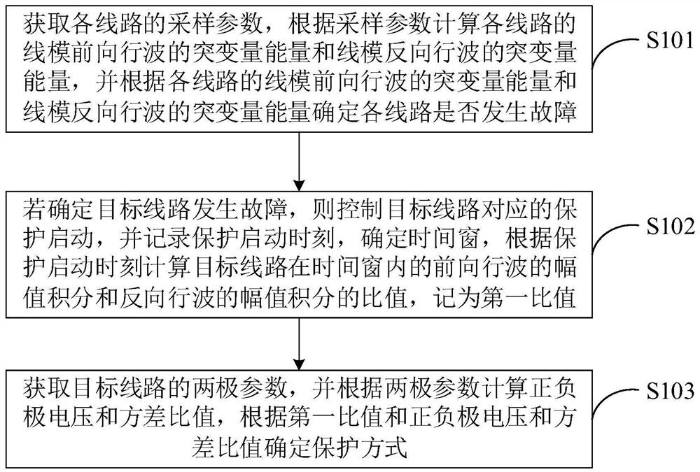
[0030] figure 1 It is a schematic diagram of the implementation flow of the longitudinal protection method provided by an embodiment of the present invention. For the convenience of description, only the parts related to the embodiment of the present inve...


PUM


Abstract

The invention is applicable to the technical field of power grid protection and discloses a longitudinal protection method, system and terminal equipment, which include: calculating the mutation amount energy of the line mode forward traveling wave and the line mode reverse traveling wave of each line according to the sampling parameters. The mutation energy determines whether each line is faulty based on the mutation energy of the forward traveling wave of the line mode and the mutation energy of the reverse traveling wave of the line mode; if it is determined that the target line is faulty, the corresponding protection of the target line is controlled. Start, record the protection start time, determine the time window, and calculate the ratio of the amplitude integral of the forward traveling wave and the amplitude integral of the reverse traveling wave of the target line within the time window based on the protection start time, record it as the first ratio; obtain For the two-pole parameters of the target line, calculate the positive and negative voltage and variance ratios based on the two-pole parameters, and determine the protection method based on the first ratio and the positive and negative voltage and variance ratios. The invention has strong resistance to transition resistance and noise interference, has no protection dead zone, and does not require synchronization.

Description

technical field [0001] The invention belongs to the technical field of power grid protection, and in particular relates to a longitudinal protection method, system and terminal equipment. Background technique [0002] As a reliable means of grid-connected renewable energy and large-capacity long-distance power transmission, DC transmission technology has received extensive attention. The "mesh structure" multi-terminal DC power grid forms a "point-to-multipoint" and "multipoint-to-point" network topology, which has the advantages of a small number of converter stations and flexible transmission methods, and is more in line with the future development direction of DC transmission. However, when a DC line fault occurs, the fault current rises rapidly, coupled with the influence of other branch circuits in the topology, which poses a huge challenge to the relay protection system, especially the design of line protection. [0003] In the prior art, the line protection of the MT...

Claims


Application Information

Patent Timeline
Patent Type & Authority Patents(China)
IPC IPC(8): H02H7/26H02H7/28G01R31/11
CPCH02H7/262H02H7/263H02H7/28G01R31/11Y02E60/60
Inventor 袁博王涛秦梁栋王颖张章张丽洁张倩茅荆志朋唐帅彭婵邵华习朋
Owner INST OF ECONOMIC & TECH STATE GRID HEBEI ELECTRIC POWER
Why Eureka
Try Eureka