

Current-limiting type single-phase bridge rectifying circuit
A rectifier circuit and single-phase bridge technology, which is applied in the field of current-limiting single-phase bridge rectifier circuit, can solve problems such as current jitter, rectifier diode burden, and normal operation damage of high-precision components, so as to avoid burden and improve working life.
- Summary
- Abstract
- Description
- Claims
- Application Information
AI Technical Summary
Problems solved by technology
Method used
Image

Examples
Embodiment 1
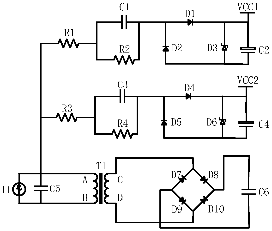
[0015] An embodiment of the present invention provides a current-limiting single-phase bridge rectifier circuit, including: a first capacitor C1, a second capacitor C2, a third capacitor C3, a fourth capacitor C4, a fifth capacitor C5, a sixth capacitor C6, a A resistor R1, a second resistor R2, a third resistor R3, a fourth resistor R4, a first diode D1, a second diode D2, a third diode D3, a fourth diode D4, a fifth two Pole tube D5, sixth diode D6, seventh diode D7, eighth diode D8, ninth diode D9, tenth diode D10, transformer T1, current source I1;
[0016] The cathode of the first diode D1 is connected to the cathode of the third diode D3, the anode of the second capacitor C2, and the first voltage source VCC1, and the anode of the first diode D1 is connected to the first capacitor C1 One end, the cathode of the second diode D2, one end of the second resistor R2, the other end of the first capacitor C1 is connected to the other end of the second resistor R2, and one end o...
PUM
 Abstract
Description
Claims
Application Information