Supercharge Your Innovation With Domain-Expert AI Agents!

Dimming method and device of pipeline detection equipment and computer terminal

A pipeline detection and light adjustment device technology, applied in the direction of electrical components, etc., can solve the problems of high quality, mentality and experience of operators, dazzling feeling, time-consuming and labor-intensive problems, etc.

Active Publication Date: 2020-06-02
SHENZHEN SCHRODER INDUSTYR MEASURE & CONTROLS EQUIP CO LTD
View PDF4 Cites 0 Cited by
  • Summary
  • Abstract
  • Description
  • Claims
  • Application Information

AI Technical Summary

Problems solved by technology

[0002] At present, many pipeline inspection equipment in my country use the video inspection method (Closed Circuit Television, referred to as CCTV) when inspecting pipelines. During the video inspection process, the lighting environment provided by the light source system has a great impact on video imaging, affecting The effect of video viewing and the quality of pipe measurement using image processing technology
[0003] On the one hand, the existing light source system for CCTV detection is manually controlled, and the staff need to adjust the light source system based on experience to meet the lighting requirements during the detection process, which is time-consuming and laborious, and due to the complexity of the pipeline environment and detection Often during operation, the video interface will be too dark for a while, and overexposed for a while, resulting in dazzling, which increases the visual fatigue of the operator when watching the video
[0004] On the other hand, with the existing technology of manually adjusting the light intensity, when the detection equipment is at the entrance and exit of the pipeline or the connecting well, the staff often needs to manually adjust the light intensity, and the process of manually adjusting the light intensity not only increases the workload of the operators , has higher requirements on the quality, mentality and experience of the operator, and also affects the detection efficiency of the detection equipment

Method used


Image

  • Dimming method and device of pipeline detection equipment and computer terminal
  • Dimming method and device of pipeline detection equipment and computer terminal
  • Dimming method and device of pipeline detection equipment and computer terminal

Examples


Embodiment 1

[0050] For this example, see Figure 4 , shows a schematic flow chart of the pipeline to be inspected according to the embodiment of the present invention. The pipeline to be inspected includes a shaft pipeline and a horizontal pipeline. Such as Figure 4 As shown, at the connection between the vertical pipe and the horizontal pipe, ambient light enters the horizontal pipe through the vertical pipe, and the horizontal pipe is divided into an area that can receive ambient light and an area that cannot receive ambient light.

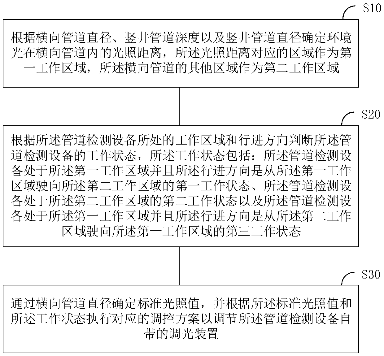
[0051] corresponds to Figure 4 The pipeline structure shown, figure 1 The method of dimming the pipeline inspection equipment is shown to include:

[0052] S10: Determine the illumination distance of the ambient light in the horizontal pipeline according to the diameter of the horizontal pipeline, the depth of the shaft pipeline, and the diameter of the vertical pipeline, the area corresponding to the illumination distance is used as the first working...

Embodiment 2

[0090] In this example, see Figure 5 , showing another schematic structural view of the pipeline to be tested.

[0091] Such as Figure 5 As shown, the pipes to be detected include multiple vertical pipes, and the ambient light is input into the horizontal pipes through the vertical pipes to form a corresponding illumination distance. The pipeline inspection equipment enters the horizontal pipeline through the vertical shaft pipeline, and the above-mentioned vertical shaft pipeline is recorded as the first vertical shaft pipeline, and the illumination distance formed by the first vertical shaft pipeline is recorded as the first illumination distance.

[0092] It can be understood that when the traveling direction of the pipeline detection equipment is away from the entrance of the horizontal pipeline, it will encounter the next vertical shaft pipeline, which is recorded as the second vertical shaft pipeline, and the illumination distance formed by the second vertical shaft p...

Embodiment 3

[0098] In this example, see Image 6 , shows a schematic diagram of the device structure of the pipeline detection equipment.

[0099] Such as Image 6 As shown, the device structure 100 of pipeline detection equipment includes: a working area division module 101 , a working status confirmation module 102 and a device light source control module 103 .

[0100] Wherein, the working area division module 101 is used to determine the illumination distance of the ambient light in the horizontal pipeline according to the diameter of the horizontal pipeline, the depth of the vertical shaft pipeline and the diameter of the vertical pipeline, and the area corresponding to the illumination distance is used as the first working area. Other areas of the transverse duct serve as the second working area.

[0101] A working status confirmation module 102, configured to judge the working status of the pipeline testing device according to the working area and the traveling direction of the p...


PUM


Abstract

The invention discloses a dimming method and device of pipeline detection equipment and a computer terminal. The method comprises the steps of determining the illumination distance of ambient light ina transverse pipeline according to the diameter of a transverse pipeline, the depth of a vertical shaft pipeline and the diameter of a vertical shaft pipeline; determining different working states ofthe pipeline detection equipment according to the illumination distance and the advancing direction of the pipeline detection equipment, determining a standard illumination value according to the diameter of the transverse pipeline, and executing a corresponding regulation and control scheme according to the standard illumination value and the working states so as to adjust a dimming device of the pipeline detection equipment. According to the technical scheme, the illumination distance of the ambient light in the pipeline is calculated according to the diameter of the detected pipeline, thenthe pipeline detection process is divided into different working areas according to the illumination distance, corresponding regulation and control schemes are executed in different working states soas to enable pipeline illumination to be maintained within the standard illumination range, and smooth operation of pipeline detection work is guaranteed.

Description

technical field [0001] The invention relates to the field of pipeline detection, in particular to a light adjustment method, device and computer terminal of pipeline detection equipment. Background technique [0002] At present, many pipeline inspection equipment in my country use the video inspection method (Closed Circuit Television, referred to as CCTV) when inspecting pipelines. During the video inspection process, the lighting environment provided by the light source system has a great impact on video imaging, affecting The effect of video viewing and the quality of pipe measurement using image processing technology. [0003] On the one hand, the existing light source system for CCTV detection is manually controlled, and the staff need to adjust the light source system based on experience to meet the lighting requirements during the detection process, which is time-consuming and laborious, and due to the complexity of the pipeline environment and detection Often during ...

Claims


Application Information

Patent Timeline
IPC IPC(8): H05B47/165
Inventor 宋有聚邹黎明
Owner SHENZHEN SCHRODER INDUSTYR MEASURE & CONTROLS EQUIP CO LTD
Features
  • R&D
  • Intellectual Property
  • Life Sciences
  • Materials
  • Tech Scout
  • Unparalleled Data Quality
  • Higher Quality Content
  • 60% Fewer Hallucinations
Learn More