Steam sterilization device for food processing
A technology for steam sterilization and food processing, applied in the field of food processing, can solve the problems of slow steam sterilization rate and low efficiency, and achieve the effects of improving contact sterilization effect, improving flow effect, and enhancing sterilization rate and work efficiency.
- Summary
- Abstract
- Description
- Claims
- Application Information
AI Technical Summary
Problems solved by technology
Method used
Image

Examples
Embodiment 1
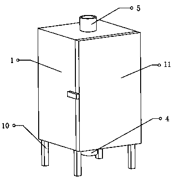
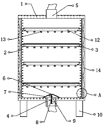
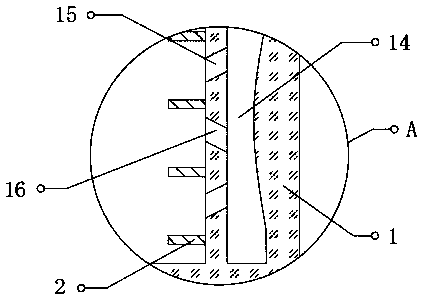
[0030] refer to Figure 1-4 , a steam sterilization device for food processing, comprising a treatment box 1 with an open end, a box door 11 is arranged at one end of the treatment box 1, and placing parts 2 distributed equidistantly are fixed on the inner walls of both sides of the treatment box 1. A plurality of placement seats 3 are slidably connected between the inner walls on both sides of the box 1, and both sides of the top and bottom outer walls of the placement seats 3 are slidably connected with the outer walls of the placement member 2, and the middle positions of the bottom and top of the treatment box 1 are respectively communicated with The air inlet pipe 4 and the air outlet pipe 5, and the air inlet pipe 4 is connected with a steam boiler through the air pipe, the top of the air inlet pipe 4 is provided with a positioning block 6, and a plurality of positioning pieces are fixed between the outer wall of the positioning block 6 and the bottom inner wall of the pr...
Embodiment 2
[0038] refer to Figure 1-5 , a steam sterilization device for food processing, a sealing block 17 with a C-shaped structure is fixed on the outer wall of the door 11 close to the processing box 1, and a matching sealing block 17 is provided on the outer wall of the processing box 1 and the position corresponding to the sealing block 17. Sealing groove, the inner wall of the sealing groove is fixed with a sealing gasket 18, and the sealing gasket 18 in the sealing groove is bonded with the sealing block 17 to improve the sealing performance;
[0039] The top and bottom of the top and bottom of the sealing block 17 are provided with a C-shaped structure on the outer wall of the door 11 near the processing box 1, and the inwall of the mounting groove is fixed with a silicone pad 19. The outer wall of 1 is close to each other, and the adhesiveness of the silica gel pad 19 and the processing box 1 is used to improve the sealing performance between the sealing block 17 and the seal...
PUM
 Abstract
Description
Claims
Application Information