Method for cultivating rhizoma paridis

A cultivation method and a technology of re-building, which are applied in planting methods, botanical equipment and methods, cultivation, etc., can solve the problems of solid fertilizers that cannot be evenly distributed and are difficult to absorb quickly, so as to enhance the effective use rate, enhance the flow effect, and promote The effect of effective release

Inactive Publication Date: 2018-09-14
DAOZHEN GELAO & MIAO AUTONOMOUS COUNTY RUIFA AGRI TECH DEV CO LTD
0 Cites 3 Cited by

AI-Extracted Technical Summary

Problems solved by technology

[0005] The present invention intends to provide a method for cultivating heavy plants to solve the p...

Abstract

The invention relates to the technical field of planting of a heavy building, and discloses a method for cultivating rhizoma paridis. The method includes land preparation, seed pretreatment, plantingpit digging, sowing and earthing. Between the planting pit digging step and the sowing step, a soil treatment step is included. The soil treatment step includes step A of turning the soil, and collecting the turned soil; step B of spraying clear water into the soil to make the soil softened and loosened; step C of stirring fertilizer, evenly mixing fertilizer and soil at a proportion of 1:20, andmaking fertilizer soil. In the earthing step, after the earthing, a plurality of vertical pipes are inserted around a planting pit, the plurality of vertical pipes are distributed around the plantingpit, the vertical pipes are provided with punched holes, and the upper ends of the vertical pipes penetrate out of the soil surface. In the soil treatment step, a soil fertilizer stirring device is adopted for automatic treatment. By the adoption of the method, the problems that solid fertilizer cannot be uniformly distributed and it is difficult to quickly absorb the solid fertilizer can be solved.

Application Domain

SpadesPlanting +5

Technology Topic

BiologySoil treatment +2

Image

  • Method for cultivating rhizoma paridis

Examples

  • Experimental program(1)

Example Embodiment

[0020] The present invention will be further described in detail below through specific implementations:
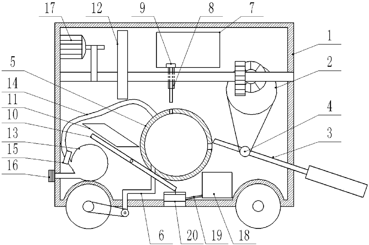
[0021] The reference signs in the drawings of the specification include: car body 1, eccentric wheel 2, rocking plate 3, belt wheel 4, soil mixing tank 5, soil discharge pipe 6, fertilizer box 7, fertilizer discharge pipe 8, latch 9, lever 10, Wedge 11, cam 12, water bladder 13, water spray pipe 14, pressure valve 15, water filling port 16, motor 17, water tank 18, drain pipe 19, plug 20.
[0022] Chonglou cultivation method, the operation steps include:
[0023] 1. Select the soil for site preparation and deep-turn the soil in the sun-inclined area.
[0024] 2. Seed pretreatment, select full, mildew-free and non-damaged Claytan seeds, soak and disinfect them with carbendazim, then place the seeds in the nutrient base solution for soaking; after the soaking is completed, place the seeds in a transparent seal Put it in the pocket and seal the bag, and wait until the seeds are white.
[0025] 3. Dig planting pits, open borders between fields, and dig planting pits.
[0026] 4. Soil treatment, including:
[0027] A. Turn the soil and collect the soil turned out;
[0028] B. Spray water, spray clear water into the soil to soften and loosen the soil;
[0029] C. Mix fertilizer, mix fertilizer and soil uniformly according to the ratio of 1:20 to make fertilizer soil;
[0030] The soil processing step uses a soil mixing device for automatic processing. The structure of the soil mixing device used in this embodiment is as follows figure 1 Shown:
[0031] It includes a car body 1, which is provided with a motor 17, a mining mechanism, a water spray mechanism, a soil mixing mechanism, and a watering mechanism.
[0032] The drive shaft belt of the motor 17 is connected with a shaft rod, the shaft rod is rotatably connected in the vehicle body 1 through a bearing, and a driving gear is fixed on the shaft rod by a key connection.
[0033] The excavation mechanism is used for turning soil and collecting soil. Its structure includes rotating an eccentric wheel 2 arranged in the vehicle body 1. The center of the eccentric wheel 2 is keyed and fixed with a driven gear. The driven gear meshes with the driving gear and is eccentric The round side of the wheel 2 is sleeved with a belt. The outer side of the eccentric wheel 2 is provided with a rocking plate 3, one end of the rocking plate 3 extends out of the car body 1, and the other end is rotatably connected in the car body 1. The middle of the rocking plate 3 is provided with a pulley 4, which is connected to the eccentric wheel 2. The other end of the belt is sleeved on the pulley 4.
[0034] The water spray mechanism is used to spray water to the soil, and its structure includes a water bladder 13, a water spray pipe 14 is connected to the water bladder 13, a pressure valve 15 is provided on the water spray pipe 14, and a water filling port 16 is also provided on the water bladder 13 , The water filling port 16 is equipped with a switch.
[0035] The soil mixing mechanism is used for mixing fertilizer, and its structure includes the soil mixing tank 5, the fertilizer box 7 and the reciprocating control mechanism. The fertilizer tank 7 is located above the soil mixing tank 5, and a fertilizer discharge pipe 8 is arranged at the bottom of the fertilizer tank 7, and a plug 9 is slidably connected in the fertilizer discharge pipe 8. The plug 9 has a cone shape, and the diameter of the upper part of the plug 9 is the same as the diameter of the fertilizer discharge pipe 8, and the diameter of the lower part of the plug 9 is smaller than the diameter of the fertilizer discharge pipe 8. The end of the water spray pipe 14 away from the water bladder 13 is connected to the soil mixing tank 5. The soil mixing tank 5 is provided with a soil inlet matching the end of the rocking plate 3 in the vehicle body 1 and a fertilizer inlet matching the fertilizer pipe 8 The soil inlet is used to transfer the soil on the rocking plate 3 into the soil mixing tank 5, the fertilizer inlet is used to transfer the fertilizer in the fertilizer box 7 to the soil mixing tank 5, and the reciprocating control mechanism is used to control the soil mixing The cylinder 5 reciprocates, and the soil mixing cylinder 5 intermittently abuts on the lower end of the plug 9 and pushes the plug 9 to slide up. The bottom of the soil mixing tank 5 is connected with a dump pipe 6, which passes through the bottom of the car body 1 and extends to the outside of the car body 1. The end of the dump pipe 6 located outside the car body 1 is connected with a valve through a one-way bearing rotation. The belt is connected with the rear wheel of the vehicle body 1. The reciprocating control mechanism includes a lever 10 that is set to rotate and is inclined. A torsion spring is connected to the fulcrum of the lever 10. The low end of the lever 10 is located on the lower side of the soil mixing tank 5 and abuts against the bottom of the soil mixing tank 5. The high end of the lever 10 A parallelogram-shaped wedge 11 is provided on the outer side. The wedge 11 includes a set of inclined opposite sides. One of the inclined opposite sides abuts on the high end of the lever 10. The shaft is also keyed with a cam 12, and the cam 12 abuts On the other of the diagonally opposite sides of the wedge 11.
[0036] The watering mechanism is used to water the seeds, and its structure includes a water tank 18 located in the car body 1, the water tank 18 is connected with a drain pipe 19, and the bottom of the car body 1 is provided with a slideway, which is connected to the drain pipe 19, and A plug block 20 with clearance fit is provided in the channel, and the plug block 20 is located at the connection part between the slide channel and the drain pipe 19, and a drawstring is connected between the plug block 20 and the bottom end of the lever 10.
[0037] The motor 17 is used as the driving source of the device to provide power for the operation of each mechanism, and the shaft is used to transmit the power of the motor 17 to the cam 12 and the driving gear to make the cam 12 and the driven gear rotate synchronously to realize the mixing mechanism and mining The synchronous work of the digging mechanism makes that when the soil is continuously mixed in the soil mixing tank 5, new soil that needs to be mixed enters the mixing tank 5 intermittently, so as to ensure that the soil delivered to the soil mixing tank 5 is It can be mixed evenly to ensure the mixing effect. The eccentric wheel 2 is used to drive the rocking plate 3 to swing and excavate the soil through the reciprocating motion of the rocking plate 3, and when the rocking plate 3 is inclined to the soil mixing tank 5, the soil can automatically slide in along the inclined surface of the rocking plate 3 In the soil mixing tank 5, the automatic soil feeding into the soil mixing tank 5 is thus realized. The lever 10 is used to intermittently lift the soil mixing tank 5 during reciprocating swing, so as to realize the reciprocating movement of the soil mixing tank 5. When the wedge 11 is squeezed by the cam 12, it moves laterally and can squeeze the high end of the lever 10 so that the lever 10 can swing automatically and thus can control the movement of the soil mixing tank 5. The water bladder 13 is used to spray water into the soil mixing tank 5. When the lever 10 swings, the high end of the lever 10 will squeeze the water bladder 13 to realize the process of the water bladder 13 spraying water into the soil mixing tank 5. 10 swings to drive the plug 20 to slide in the slideway to connect the drainage pipe 19 with the slideway, so that the water in the water tank 18 can flow into the planting pit along the drainage pipe 19 and the slideway to irrigate the planting pit.
[0038] When in use, the fertilizer can be installed in the fertilizer tank 7, and the water bladder 13 can be filled with clean water from the water filling port 16. The motor 17 is activated to push the car body 1 to travel on the border. At this time, the valve on the dump tube 6 is restricted by the one-way bearing and does not follow the rotation of the rear wheel of the car body 1, so the dump tube 6 is in a closed state. The motor 17 drives the shaft connected with the belt to rotate, so that the cam 12 on the shaft and the driving gear follow to rotate. The driving gear pushes the engaged driven gear to rotate, and the driven gear drives the fixedly connected eccentric wheel 2 to rotate. The diameter end keeps pressing against the upper end of the belt to push the belt up. The lower end of the belt drives the pulley 4 to move up to make the rocking plate 3 swing up. When the long diameter end of the eccentric wheel 2 moves away from the upper end of the belt, the upper end of the belt again Put the rocking plate 3 down, so that the rocking plate 3 reciprocates. The end of the rocking plate 3 located outside the car body 1 swings back and forth to shovel the soil intermittently. When the rocking plate 3 is inclined to the soil mixing tank 5, the shoveled soil is moved along the inclined rocking plate 3 and the soil mixing tank 5. The soil mouth enters the soil mixing tank 5 to realize the automatic introduction of soil. At the same time, the long-diameter end of the cam 12 continuously abuts against an inclined surface of the wedge 11 during the rotation, and pushes the wedge 11 away from the soil mixing tank 5, and the other inclined surface of the wedge 11 squeezes the high end of the lever 10 to make the lever 10 swings and deforms the torsion spring. The low end of the lever 10 follows the swing to push the soil mixing tank 5 up. The soil mixing tank 5 abuts on the pin 9 and pushes the pin 9 to slide in the fertilizer discharge pipe 8. A gap is formed between the lower end and the fertilizer discharge pipe 8, and the fertilizer in the fertilizer box 7 falls through the gap and enters the soil mixing tank 5 through the fertilizer inlet on the soil mixing tank 5. When the high end of the lever 10 is squeezed and deflected by the wedge 11, the water bladder 13 is squeezed and the pressure in the water bladder 13 increases. The pressure valve 15 on the water spray pipe 14 is opened, and the water in the water bladder 13 is released The water spray pipe 14 is sprayed into the soil mixing tank 5 and sprayed on the soil to soften the soil, facilitate the full mixing between the soil and the fertilizer, and facilitate the growth and germination of seeds. Then, the long-diameter end of the cam 12 is far away from the wedge 11, the high end of the lever 10 pushes the wedge 11 to reset under the action of the torsion spring, the low end of the lever 10 is away from the soil mixing tank 5, and the soil mixing tank 5 automatically falls under the action of gravity , Because the soil mixing tank 5 relies on the thrust of the lever 10 when it rises, and relies on its own gravity when falling, because the speed of the soil mixing tank 5 reciprocating is different, so that the soil in the soil mixing tank 5 is The fertilizer is mixed by relative movement. After the soil mixing tank 5 is dropped, the flap is tilted again to send the shoveled soil into the soil mixing tank 5 again for mixing, so as to ensure that the fertilizer and the soil are evenly mixed. After the soil mixing tank 5 is lowered, the bolt 9 falls back under the action of gravity to block the fertilizer discharge pipe 8 through its large diameter end.
[0039] During the continuous swing of the lever 10, the plug 20 is pulled by the rope to slide in the slideway to open the connection between the drain pipe 19 and the slideway. The water in the water tank 18 is discharged from the drain pipe 19 and the slideway to the border. Water the planting pit on the border.
[0040] 5. Sowing seeds, sowing the seeds in the planting pit.
[0041] 6. Cover the soil, turn off the motor 17, and pull the car body 1 back. The rear wheel of the car body 1 drives the valve on the drain pipe 6 to turn through the belt to open the drain pipe 6, and the mixed soil in the soil mixing tank 5 is discharged from the drain pipe. 6 Drain into the planting pit to realize automatic soil covering of the planting pit, which is convenient for batch planting and cultivation of heavy buildings. Then a plurality of vertical pipes are inserted around the planting pit, and the plurality of vertical pipes are evenly distributed around the planting pit, and the vertical pipes are all provided with perforations, and the upper ends of the vertical pipes are all penetrated out of the soil surface.
[0042] Several vertical pipes have a diversion effect on the waste in the soil. When the fertilizer is dissolved by rainwater, it can flow along the vertical pipe to the deep layer of the soil, thereby reducing the loss of fertilizer. It is good for the seeds to absorb nutrients from each layer of soil after they take root, and promote the growth of the heavy building. In addition, the vertical pipe can introduce external air into the soil, which not only enhances the oxygen content of the soil, promotes the aerobic respiration of seeds, but also promotes the release of fertilizer efficiency and enhances the effective utilization rate of waste materials.
[0043] Using the soil mixing method in the present invention to cultivate the Chonglou, not only can better germinate and take root, but also the germination period of the seeds is significantly shortened. Compared with the prior art method of directly covering the soil and then fertilizing the cultivation method, the Chonglou can promote the nutrients It is effectively absorbed, and the harvested Chonglou has the advantages of large main root tuber, many and long roots.
[0044] The above are only the embodiments of the present invention, and common knowledge such as specific technical solutions and/or characteristics known in the solutions are not described herein. It should be pointed out that for those skilled in the art, without departing from the technical solution of the present invention, several modifications and improvements can be made. These should also be regarded as the protection scope of the present invention, and these will not affect the implementation of the present invention. The effect and practicality of the patent. The scope of protection claimed in this application shall be subject to the content of the claims, and the specific implementation modes in the description can be used to interpret the content of the claims.

PUM

no PUM

Description & Claims & Application Information

We can also present the details of the Description, Claims and Application information to help users get a comprehensive understanding of the technical details of the patent, such as background art, summary of invention, brief description of drawings, description of embodiments, and other original content. On the other hand, users can also determine the specific scope of protection of the technology through the list of claims; as well as understand the changes in the life cycle of the technology with the presentation of the patent timeline. Login to view more.

Similar technology patents

Nano magnetic massager

Owner:上海谷律信息科技有限公司

Heat dissipation type anti-sticking injection mold

PendingCN114228080AImprove the flow effectsave human effort
Owner:SUZHOU BADOU ELECTRONICS TECH CO LTD

Steam sterilization device for food processing

InactiveCN111227158AImprove the flow effectImprove contact sterilization effect
Owner:六安科科达尔生物科技有限公司

Low-temperature electrolyte and lithium ion battery containing same

PendingCN114552009AIncrease oxygen contentIncrease dissociation
Owner:HEFEI GUOXUAN HIGH TECH POWER ENERGY

Preparation method of cow-dung fish feed

InactiveCN107874034Aincrease oxygen contentreduce germs
Owner:张容

Oxygenation bridge

InactiveCN101311129Aincrease oxygen contentImprove the ecological environment
Owner:SHANGHAI HIGH SCHOOL

Classification and recommendation of technical efficacy words

  • Improve the flow effect

Heat dissipation type anti-sticking injection mold

PendingCN114228080AImprove the flow effectsave human effort
Owner:SUZHOU BADOU ELECTRONICS TECH CO LTD

Steam sterilization device for food processing

InactiveCN111227158AImprove the flow effectImprove contact sterilization effect
Owner:六安科科达尔生物科技有限公司
Why Eureka
Try Eureka