Low-voltage energy-saving equipment

An energy-saving equipment and low-voltage technology, which is applied in the field of energy-saving equipment, can solve problems such as short circuit between phases or intermittent discharge, poor contact points, and narrow space, so as to prevent insufficient bonding force, avoid gas non-circulation, and enhance bonding force Effect

Active Publication Date: 2020-12-11
广州优易机械科技有限公司
View PDF8 Cites 0 Cited by
  • Summary
  • Abstract
  • Description
  • Claims
  • Application Information

AI Technical Summary

Problems solved by technology

[0002] The role of the transformer in the power system is to transform the voltage to facilitate power transmission. After the voltage is boosted by the step-up transformer, it can reduce line loss, improve the economy of power transmission, and achieve the purpose of long-distance power transmission. The step-down transformer It can change the high voltage into the various levels of voltage required by the user to meet the needs of the user. However, due to the poor contact of the l

Method used


Image

  • Low-voltage energy-saving equipment
  • Low-voltage energy-saving equipment
  • Low-voltage energy-saving equipment

Examples


Embodiment 1

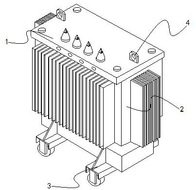
[0023] Such as Figure 1-Figure 5 Shown:

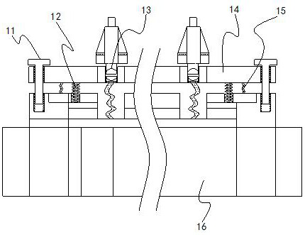
[0024] A low-voltage energy-saving device of the present invention, its structure includes a connection mechanism 1, a transformer 2, a slider 3, and a fixed lifting lug 4, the fixed lifting lug 4 is welded on the surface of the connection mechanism 1, and the transformer 2 is installed on the connection mechanism 1 The lower end of the slider 3 is embedded in the lower end of the transformer 2. The connecting mechanism 1 is provided with a threaded rod 11, a first spring rod 12, a fixing mechanism 13, a connecting plate 14, a folding mechanism 15, and a welding plate 16. The threaded rod 11 runs through the inside of the connecting plate 14, the lower end of the first spring rod 12 is connected to the upper end of the welding plate 16, the fixing mechanism 13 is installed inside the connecting plate 14, and the folding mechanism 15 is installed on the welding plate 16 and embedded in the lower end of the connection plate 14, the wel...

Embodiment 2

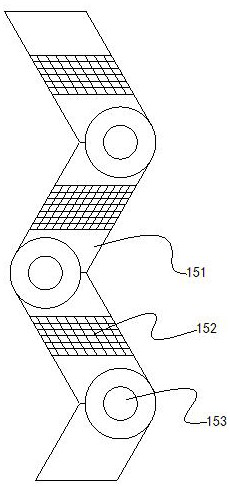
[0031] Such as Figure 6-Figure 7 Shown:

[0032]Wherein, the fixing mechanism 13 is provided with a fixing plate a1, a metal rod a2, a second spring rod a3, a compression plate a4, a bearing a5, a bonding mechanism a6, a rotating rod a7, a circular hole a8, and the second spring rod The lower end of a3 is embedded on the surface of the fixed plate a1, the metal rod a2 runs through the middle of the fixed plate a1, the upper end of the second spring rod a3 is welded to the lower end of the compression plate a4, and the compression plate a4 is connected to the fitting mechanism a6 for clearance fit, the lamination mechanism a6 is installed in the middle of the bearing a5, the outer side of the bearing a5 is embedded in the inside of the rotating rod a7, the circular hole a8 is located above the metal rod a2, and the fixing plate a1 is attached to the inside of the connection plate 14, the middle of the compression plate a4 is a metal sheet, and the surface is provided with a h...


PUM


Abstract

The invention discloses low-voltage energy-saving equipment, which structurally comprises a connecting mechanism, a transformer, a slider and a fixed lifting lug, the connecting mechanism is providedwith a threaded rod, a first spring rod, a fixed mechanism, a connecting plate, a folding mechanism and a welding plate, and a rotating disc in a circulating mechanism rotates through a connecting rod, so that a gap in a gap mechanism circulates air; the blocking disc is a disc with a hollow hole in the middle, congestion formed after accumulation of a large amount of heat is avoided, the emissionrate is prevented from being reduced, the flowing effect is improved, dust is filtered through a filter screen, the effect of internal gas circulation is achieved, the problem that gas does not circulate during heat emission is solved, and a friction force between the tapping point and the compression plate is enhanced through the rubber block; and through sliding fit of a connecting ring and a bearing, the situation that an attaching mechanism drives the tapping point to rotate when the rotating rod rotates in a threaded mode is avoided, the attaching force of the tapping point on the surface of the compression plate is enhanced, and the intermittent circuit connection problem caused by insufficient tapping point attaching force is prevented.

Description

technical field [0001] The invention relates to the field of energy-saving equipment, in particular to a low-voltage energy-saving equipment. Background technique [0002] The role of the transformer in the power system is to transform the voltage to facilitate power transmission. After the voltage is boosted by the step-up transformer, it can reduce line loss, improve the economy of power transmission, and achieve the purpose of long-distance power transmission. The step-down transformer It can change the high voltage into the various levels of voltage required by the user to meet the needs of the user. However, due to the poor contact of the low-voltage wire tap, the contact sheet is overheated, and the internal space is relatively narrow, causing heat to concentrate inside, and the heat rises. High is easy to cause a short circuit, and the contact between the contact piece and the tap is completed under the elastic force of the contact piece, and the contact point is easi...

Claims


Application Information

Patent Timeline
IPC IPC(8): H01F27/08H01F27/28H01F27/04
CPCH01F27/04H01F27/08H01F27/28
Inventor 张行凤
Owner 广州优易机械科技有限公司
Why Eureka
Try Eureka