Heat dissipation type anti-sticking injection mold

A technology of injection molds and anti-sticking materials, which is applied in the field of injection molds, can solve problems such as increasing the workload of staff, water overflow, and no guarantee of water addition, so as to improve the processing effect, improve the processing ability, and reduce manpower.

Pending Publication Date: 2022-03-25
SUZHOU BADOU ELECTRONICS TECH CO LTD
1 Cites 0 Cited by

AI-Extracted Technical Summary

Problems solved by technology

But its disadvantage is: there is no guarantee of the amount of water added...

Method used

After unloading is finished, open dust blowing gun 49, positive and negative motor 43, lighting lamp 47 and camera 48, control linear motor 41 to move, dust blowing gun 49 auxiliary air nozzles 46 carry out blowing in moving process, cooperate again The rotation of the positive and negative motor 43 ensures the cleaning effect on the first mold 1 and the second mold 2. Cooperating with the expansion and contraction of the electric telescopic rod 44, the treatment effect is improved. If the treatment effect is insufficient, the linear motor 41 can also be controlled to reciprocate to improve the cleaning effect. processing capacity.
With reference to Fig. 1 and Fig. 5, in order to clean mold one and mold two, and when product is not unloaded, blow product, auxiliary blanking, cleaning combination 4 comprises two linear motors that are connected with adjustment combination 3 41. The assembly plate 42 connected to the bottom of the two linear motors 41, the positive and negative motor 43 connected to the bottom of the assembly plate 42, the hydraulic rod 35 assembled and connected to the positive and negative motor 43, the hollow tube 45 connected to the bottom of the hydraulic rod 35 1. The air nozzles 46 arranged equidistantly on the periphery of the hollow tube 45, the periphery of the hollow pipe 45 is also connected with a lighting lamp 47 and a camera 48, and the bottom end of the adjustment combination 3 is also connected with a dust blowing gun 49, the dust blowing gun 49 is prior art, cooperates air nozzle 46, realizes the cleaning to mold one 1 and mold two 2, and air blowing, can cooperate auxiliary demoulding combination 5 to promote demoulding effect, dust blowing gun 49 passes connecting pipe and air nozzle 46 Connected, after the unloading is completed, open the dust blowing gun 49, the positive and negative motor 43, the lighting lamp 47 and the camera 48, control the linear moto...

Abstract

The invention discloses a heat dissipation type anti-sticking injection mold, and belongs to the technical field of injection molds, the heat dissipation type anti-sticking injection mold comprises a first mold and a second mold arranged on the side face of the first mold, the first mold and the second mold are connected with an adjusting combination, and the adjusting combination is connected with a cleaning combination; the periphery of the first mold and the periphery of the second mold are both connected with liquid containing shells, a liquid storage box is arranged below the adjusting combination, the side face of the liquid storage box is connected with two liquid extraction pumps, the liquid extraction pumps communicate with the liquid storage box through water pipes, the liquid extraction pumps communicate with the liquid containing shells through first connecting pipes, and the second connecting pipes communicate with the liquid containing shells through second connecting pipes. The liquid storage tank is communicated with the liquid containing shell through a second connecting pipe and a third connecting pipe, a semiconductor chilling plate is connected to the inner wall of the liquid storage tank, and the adjusting assembly comprises a C-shaped supporting table, two vertical plates connected to the top end of the supporting table and a mounting plate connected to the top ends of the vertical plates. The heat dissipation type anti-material-sticking injection mold not only can dissipate heat and prevent material sticking, but also can facilitate automatic discharging.

Technology Topic

Image

  • Heat dissipation type anti-sticking injection mold
  • Heat dissipation type anti-sticking injection mold
  • Heat dissipation type anti-sticking injection mold

Examples

  • Experimental program(1)

Example Embodiment

[0027] In the following description, numerous specific details are set forth in order to provide a more thorough understanding of the present invention. It will be apparent, however, to one skilled in the art that the present invention may be practiced without one or more of these details. In other instances, some technical features known in the art have not been described in order to avoid obscuring the present invention.
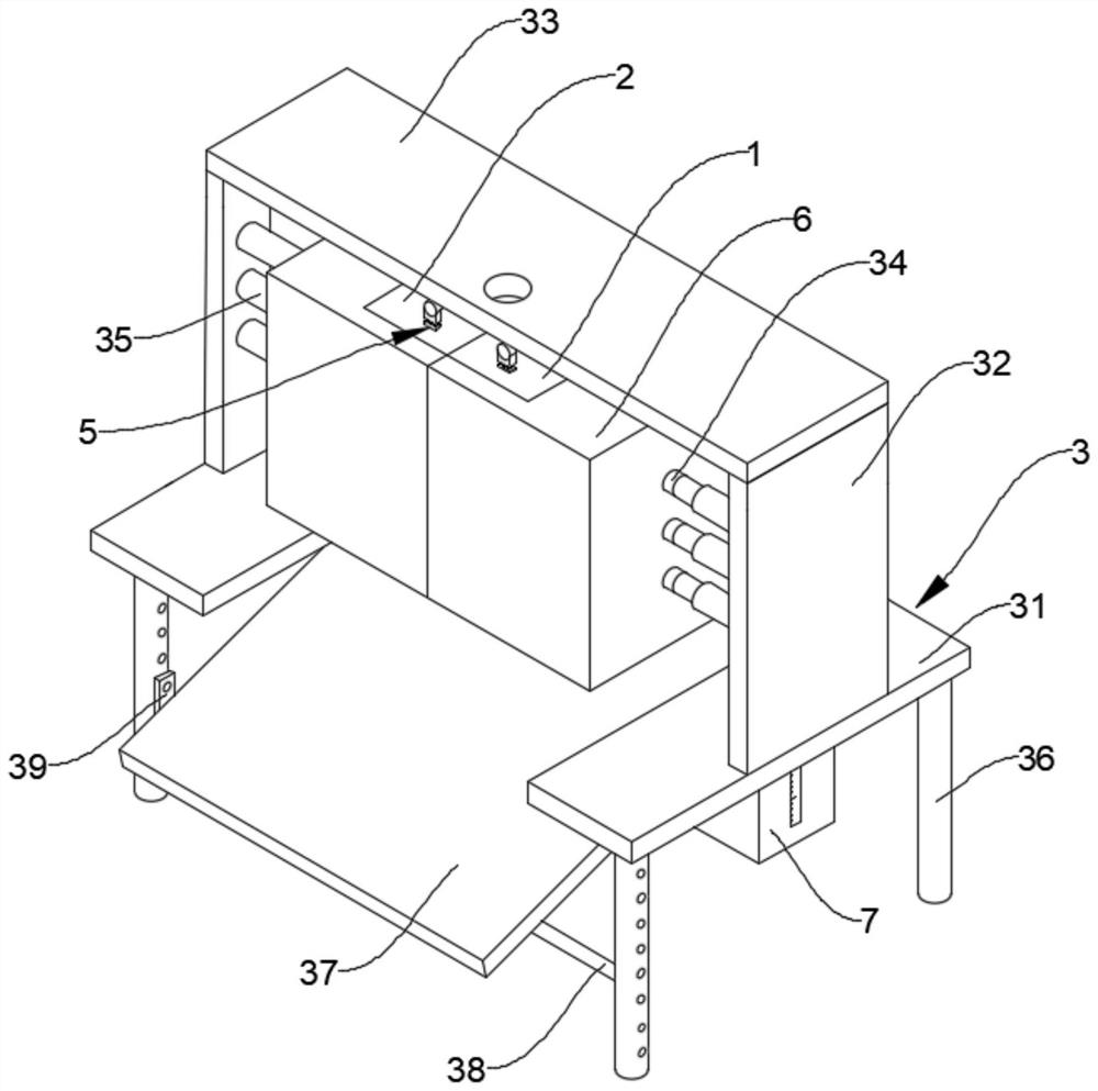
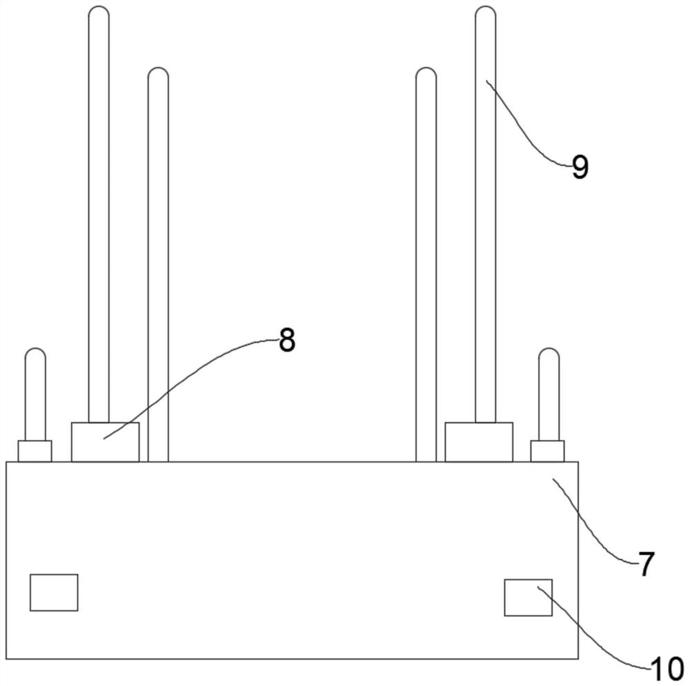
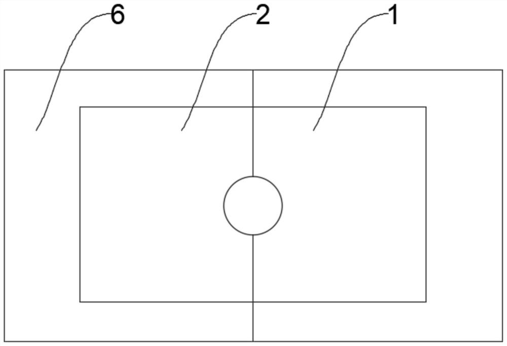
[0028] The present invention provides such as figure 1 and figure 2 Shown is a heat-dissipating and anti-sticking material injection mold, including a mold one 1 and a mold two 2 arranged on the side of the mold one 1, the mold one 1 and the mold two 2 have their own storage cavities, used for molding products, molds. The first 1 and the second mold 2 are connected with the adjustment combination 3, and the adjustment combination 3 is connected with the cleaning combination 4; the outer periphery of the mold one 1 and the mold two 2 are connected with a liquid-containing shell 6, and the liquid-containing shell 6 wraps the mold one 1 and the mold two. 2. The peripheral liquid tank is used to hold the water liquid to contact with the mold one 1 and the mold two 2 to realize heat dissipation and cooling, and a liquid storage tank 7 is provided below the adjustment combination 3, and the side of the liquid storage tank 7 is connected with two The suction pump 8, the suction pump 8 is communicated with the liquid storage tank 7 through the water pipe, and the suction pump 8 is communicated with the liquid-containing shell 6 through the connecting pipe 9, and the highest position of the connecting pipe 3 is lower than the highest position of the connecting pipe 9. , the highest point of the connecting pipe 2 is lower than the highest point of the connecting pipe three, the liquid storage tank 7 is communicated with the liquid-containing shell 6 through the connecting pipe two and the connecting pipe three, and the inner wall of the liquid storage tank 7 is connected with a semiconductor refrigeration sheet 10, and the semiconductor refrigeration The heat-absorbing part of the sheet 10 is arranged in the inner cavity of the liquid storage tank 7, the heat-releasing part of the semiconductor refrigeration sheet 10 is arranged outside the liquid storage tank 7, and an observation groove is opened on the side of the liquid storage tank 7, and the inner wall of the observation groove An observation window with a scale line is connected, and a solenoid valve is installed on the second connecting pipe. After the injection molding is completed, the water is pumped into the liquid container 6 by the liquid pump 8, and the excess water is returned to the storage with the third connecting pipe. When the liquid tank 7 needs to increase the flow effect, the solenoid valve of the second connecting pipe can be opened. After the product is formed, the liquid pump 8 is closed.
[0029] refer to figure 1 , Figure 4 and Figure 5 , in order to facilitate unloading and automatic unloading, the adjustment combination 3 includes a C-shaped support table 31, two vertical plates 32 connected to the top of the support table 31, a mounting plate 33 connected to the top of the vertical plate 32, a mold one 1 and a A plurality of connecting rods 34 are connected to the sides of the second mold 2, and the connecting rods 34 extend through the liquid-containing casing 6 to the outside of the liquid-containing casing 6. The two vertical plates 32 are connected to the connecting rods through a plurality of parallel hydraulic rods 35. 34 is connected and fixed, the hydraulic rod 35 is designed so that the positions of the mold one 1 and the mold two 2 can be adjusted, the bottom end of the support table 31 is connected with a plurality of support legs 36, and the support table 31 is hinged with a feeding plate 37, two of which are A support rod 38 for supporting the feeder plate 37 is arranged between the support legs 36, and side support plates 39 are connected to both sides of the support rod 38. The side support plates 39 are connected and fixed with the support legs 36 by connecting bolts. There are a plurality of threaded through holes adapted to the connecting bolts on the side. By adjusting the position of the connecting bolts, the position of the support rod 38 can be adjusted, thereby changing the inclination of the receiving plate 37, controlling the hydraulic rod 35 to shrink, and the mold 1 1 After being pulled apart from the mold 2 2, the product falls onto the material receiving plate 37 with gravity, and then falls into the material receiving equipment.
[0030] refer to figure 1 and Figure 5, in order to clean the mold 1 and the mold 2, and when the product is not unloaded, blow the product to assist the blanking, the cleaning combination 4 includes two linear motors 41 connected to the adjustment combination 3, connected to the two linear motors 41 The assembly plate 42 at the bottom end, the positive and negative motor 43 connected to the bottom end of the assembly plate 42, the hydraulic rod 35 assembled and connected to the positive and negative motor 43, the hollow tube 45 connected to the bottom end of the hydraulic rod 35, the Equidistantly arranged air nozzles 46, the outer circumference of the hollow tube 45 is also connected with a lighting lamp 47 and a camera 48, and the bottom end of the adjustment combination 3 is also connected with a dust blowing gun 49, the dust blowing gun 49 is the prior art, with the air nozzle 46. ​​Realize the cleaning of the mold one 1 and the mold two 2, and blow air, which can cooperate with the auxiliary demoulding combination 5 to improve the demoulding effect. The dust blowing gun 49 is communicated with the air nozzle 46 through the communication pipe. The dust blowing gun 49, the positive and negative motor 43, the lighting lamp 47 and the camera 48 control the movement of the linear motor 41. During the moving process, the dust blowing gun 49 assists the air nozzle 46 to blow air, and then cooperates with the rotation of the positive and negative motor 43 to ensure that the mold is not damaged. The cleaning effect of the first 1 and the mold 2 2 is combined with the expansion and contraction of the electric telescopic rod 44 to improve the processing effect. If the processing effect is insufficient, the linear motor 41 can be controlled to reciprocate to improve the processing ability.
[0031] refer to figure 1 and image 3 , In order to facilitate the introduction of materials, the tops of the liquid housing 6 and the liquid storage tank 7 are provided with ventilation channels, the tops of the mold one 1 and the mold two 2 are provided with semi-cylindrical feed grooves, and the top of the adjustment combination 3 is provided with Feed channels corresponding to the two feed troughs.
[0032] refer to figure 1 and Image 6 , In order to assist the demoulding and improve the demoulding effect by vibration, the bottom end of the mounting plate 33 is also connected with two slide rails, the slide rails are slidably connected with sliders, and the two sliders are connected to the mold one and the mold through the auxiliary rod 11 respectively. The second 2 is connected and fixed. The top and bottom ends of the first mold 1 and the second mold 2 are connected with an auxiliary demoulding assembly 5. The auxiliary demoulding assembly 5 includes a motor seat 52, a micro motor 51 and an eccentric wheel 53. The bottom end of the micro motor 51 The motor base 52 is connected, the output shaft of the micro motor 51 is connected with a rotating rod through a coupling, and the outer circumference of the rotating rod is connected with a plurality of eccentric wheels 53 arranged side by side, and the rotation of the eccentric wheel 53, and then the mold one 1 and the mold two are connected. 2. Intermittent vibration is performed to assist demoulding. The rotating rod is connected with a stabilizer plate 54 through a bearing. The motor seat 52 and the bottom of the stabilizer plate 54 are provided with a horizontal plate 55. The horizontal plate 55 is connected with the motor seat 52 and the stabilizer plate 54. There are multiple pressure springs 56, and the expansion and contraction of the pressure springs 56 can play a protective role.
[0033] Working principle, this heat-dissipating and anti-sticking material injection mold, the injection molding equipment introduces the material into the feeding tank through the feeding channel. The water liquid falls back to the liquid storage tank 7 along with the connecting pipe 3. When the flow effect needs to be increased, the solenoid valve of the connecting pipe 2 can be opened. After the product is formed, the suction pump 8 is closed, and then the hydraulic rod 35 is controlled to shrink. After the mold 22 is pulled apart, the product falls onto the material receiving plate 37 with gravity, and then falls into the material receiving equipment.
[0034] After the unloading is completed, the dust blowing gun 49, the forward and reverse motors 43, the lighting lamp 47 and the camera 48 are turned on, and the linear motor 41 is controlled to move. The rotation of 43 ensures the cleaning effect of mold one 1 and mold two 2. In conjunction with the expansion and contraction of the electric telescopic rod 44, the processing effect can be improved. If the processing effect is insufficient, the linear motor 41 can be controlled to reciprocate to improve the processing ability. .
[0035] Finally, it should be noted that the above descriptions are only the preferred contents of the present invention, and are not intended to limit the present invention.

PUM

no PUM

Description & Claims & Application Information

We can also present the details of the Description, Claims and Application information to help users get a comprehensive understanding of the technical details of the patent, such as background art, summary of invention, brief description of drawings, description of embodiments, and other original content. On the other hand, users can also determine the specific scope of protection of the technology through the list of claims; as well as understand the changes in the life cycle of the technology with the presentation of the patent timeline. Login to view more.

Similar technology patents

Method for cultivating rhizoma paridis

InactiveCN108521904AImprove the flow effectPromotes sprout growthSpadesPlantingBiologySoil treatment
Owner:DAOZHEN GELAO & MIAO AUTONOMOUS COUNTY RUIFA AGRI TECH DEV CO LTD

Steam sterilization device for food processing

InactiveCN111227158AImprove the flow effectImprove contact sterilization effectFood preservationProcess engineeringEngineering
Owner:六安科科达尔生物科技有限公司

Low-voltage energy-saving equipment

Owner:广州优易机械科技有限公司

Classification and recommendation of technical efficacy words

  • Save human effort
  • Improve the flow effect

Method for cultivating rhizoma paridis

InactiveCN108521904AImprove the flow effectPromotes sprout growthSpadesPlantingBiologySoil treatment
Owner:DAOZHEN GELAO & MIAO AUTONOMOUS COUNTY RUIFA AGRI TECH DEV CO LTD

Steam sterilization device for food processing

InactiveCN111227158AImprove the flow effectImprove contact sterilization effectFood preservationProcess engineeringEngineering
Owner:六安科科达尔生物科技有限公司

Low-voltage energy-saving equipment

Owner:广州优易机械科技有限公司
Why Eureka
Try Eureka