Fracture bone setting assistant fixing equipment used in orthopedics department

A kind of fixation equipment and orthopedic technology, applied in the field of medical equipment, can solve the problems of easy sliding, inconvenient adjustment, and easy instability of bone joints, etc., and achieve good fixation effect, strong device adaptability, and not easy to slide

Inactive Publication Date: 2020-06-05
李庆磊
View PDF1 Cites 8 Cited by
  • Summary
  • Abstract
  • Description
  • Claims
  • Application Information

AI Technical Summary

Problems solved by technology

Therefore, an object of the present invention is to provide an auxiliary fixation device for bone fractures in orthopedics, which is mainly used to fix the angle of the auxiliary fixation device for bone fixation after the angle adjustment. It is prone to instability, and at the same time, it is inconvenient to adjust the auxiliary bone fixation equipment to suit limbs of different thicknesses.

Method used


Image

  • Fracture bone setting assistant fixing equipment used in orthopedics department
  • Fracture bone setting assistant fixing equipment used in orthopedics department
  • Fracture bone setting assistant fixing equipment used in orthopedics department

Examples


Embodiment 1

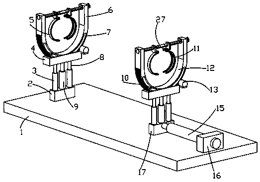
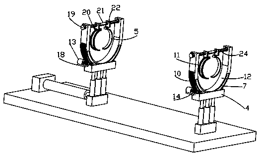
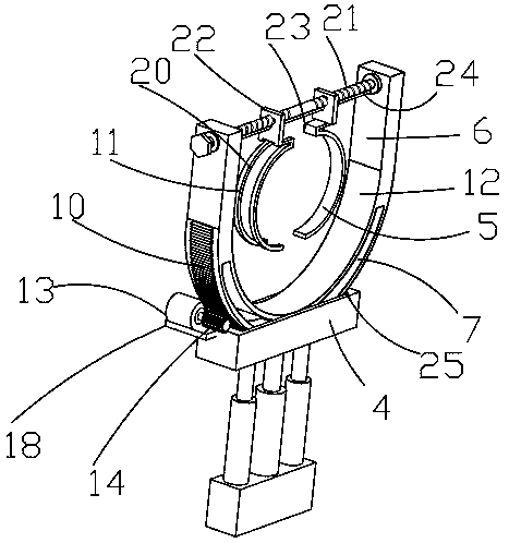
[0030] Such as Figure 1-4 The shown auxiliary fixation device for bone fractures in orthopedics includes a base plate 1, a first electric telescopic rod 9, a drive motor 13 and a second electric telescopic rod 15, the first electric telescopic rod 9, a drive motor 13 and a second electric telescopic rod The rods 15 are all electrically connected to the external power supply, the drive motor 13 is a lock-type servo motor, the left and right ends of the top of the bottom plate 1 are respectively fixedly connected with the straight block 2 and the installation block 16, and the side wall of the installation block 16 is fixedly connected with the second motor. Telescopic rod 15, the telescopic end of the second electric telescopic rod 15 is fixedly connected with slide block 17, and the top of slide block 17 and straight block 2 is fixedly connected with the first electric telescopic rod 9, and the top of the telescopic rod of the first electric telescopic rod 9 is fixedly connect...

Embodiment 2

[0032] Such as Figure 1-4As shown, a kind of orthopedics auxiliary fixation device for bone fracture, including base plate 1, first electric telescopic rod 9, driving motor 13 and second electric telescopic rod 15, first electric telescopic rod 9, driving motor 13 and second electric telescopic rod The rods 15 are all electrically connected to the external power supply, the drive motor 13 is a lock-type servo motor, the left and right ends of the top of the bottom plate 1 are respectively fixedly connected with the straight block 2 and the installation block 16, and the side wall of the installation block 16 is fixedly connected with the second motor. Telescopic rod 15, the telescopic end of the second electric telescopic rod 15 is fixedly connected with slide block 17, and the top of slide block 17 and straight block 2 is fixedly connected with the first electric telescopic rod 9, and the top of the telescopic rod of the first electric telescopic rod 9 is fixedly connected T...

Embodiment 3

[0034] Such as Figure 1-4 As shown in the figure, an auxiliary fixation device for bone fractures and osteosynthesis in orthopedics includes a base plate 1, a first electric telescopic rod 9, a driving motor 13 and a second electric telescopic rod 15, the driving motor 13 is a lock-type servo motor, and the left and right sides of the top of the bottom plate 1 The ends are respectively fixedly connected with the straight block 2 and the installation block 16, the side wall of the installation block 16 is fixedly connected with the second electric telescopic rod 15, and the telescopic end of the second electric telescopic rod 15 is fixedly connected with the slider 17, and the slider 17 and the straight The top of the block 2 is fixedly connected with the first electric telescopic rod 9, the top of the telescopic rod of the first electric telescopic rod 9 is fixedly connected with the support plate 4, the slider 17 and the top of the straight block 2 are symmetrically fixedly c...


PUM


Abstract

The invention relates to the technical field of medical instruments and discloses fracture bone setting assistant fixing equipment used in an orthopedics department. The equipment comprises a bottom plate, wherein the bottom plate is provided with a straight block and a mounting block; the mounting block is provided with a second electronic telescopic rod; the second electronic telescopic rod is provided with a sliding block; the sliding block and the straight block are provided with first electronic telescopic rods; the first electronic telescopic rods are provided with support plates; the support plates are provided with arc-shaped chutes; the arc-shaped chutes are provided with support round rods; the support plates are provided with semicircular plates; the semicircular plates are provided with arc-shaped grooves; the semicircular plates and the support plates are provided with angle adjusting mechanisms; the semicircular plates are provided with straight plates; the straight plates are provided with threaded rods; the threaded rods are provided with moveable blocks; left L-shaped blocks and right L-shaped blocks are fixedly connected with bottoms of the moveable blocks; the bottoms of the left L-shaped blocks are fixedly connected with left semicircular plates; the bottoms of the right L-shaped blocks are fixedly connected with right semicircular plates; both the right L-shaped blocks and the right semicircular plates are provided with limiting grooves; and the limiting grooves are in fitted sliding connection with the left L-shaped blocks and the left semicircular plates. Limbs of different sizes are placed between the left semicircular plates and the right semicircular plates, and thus the device is good in adaptability.

Description

technical field [0001] The invention relates to the technical field of medical devices, in particular to an auxiliary fixation device for fractures and osteosynthesis used in orthopedics. Background technique [0002] Orthopedics is also called orthopedics. It is a profession or discipline of medicine, specializing in the study of the anatomy, physiology and pathology of the musculoskeletal system, using drugs, surgery and physical methods to maintain and develop the normal form and function of this system, and to treat injuries and diseases of this system. Orthopedics is also called orthopedics. It is a profession or discipline of medicine, specializing in the study of the anatomy, physiology and pathology of the musculoskeletal system, using drugs, surgery and physical methods to maintain and develop the normal form and function of this system, and to treat injuries and diseases of this system. [0003] Now the orthopedics department of the hospital carries out bone sett...

Claims


Application Information

Patent Timeline
Patent Type & Authority Applications(China)
IPC IPC(8): A61B17/88A61B90/14
CPCA61B17/8866A61B90/14
Inventor 李庆磊
Owner 李庆磊
Why Eureka
Try Eureka