

Constant-temperature furnace for photo-thermal synergistic reaction
A technology of photothermal synergy and constant temperature furnace, which is applied in the field of constant temperature furnace, can solve the problems of unsuitable light, inability to realize photothermal synergistic reaction, and limit the development of photothermal synergistic reaction, achieve good heating uniformity, ensure light transmission and filter Light effect, easy to disassemble and replace windows and filters and maintenance
- Summary
- Abstract
- Description
- Claims
- Application Information
AI Technical Summary
Problems solved by technology
Method used
Image

Examples
Embodiment 1
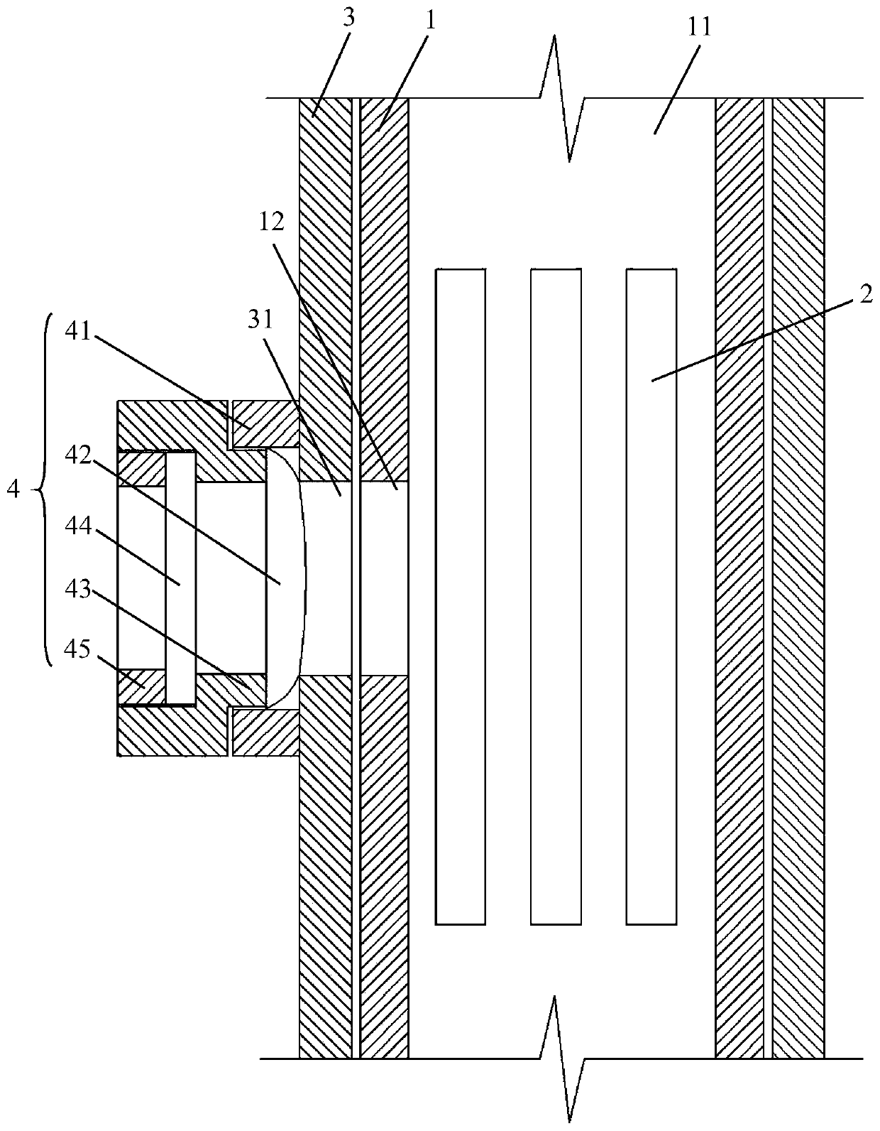
[0043] See attached figure 1 , the embodiment of the present invention discloses a constant temperature furnace for photothermal synergistic reaction, including: an inner furnace body 1, a heating body 2, an outer shell body 3 and a light-transmitting component 4;
[0044] The inner furnace body 1 is a closed structure with a furnace 11, and the side wall of the inner furnace body 1 is provided with an inner light-transmitting hole 12;
[0045] The heating body 2 is evenly fixed on the inner surface of the inner furnace body 1, and is used to heat the furnace 11;
[0046] The outer casing 3 is sealed and wrapped around the outer side of the inner furnace body 1, and the side wall is provided with an outer light-transmitting hole 31 corresponding to the inner light-transmitting hole 12;
[0047] The light-transmitting component 4 is detachably and hermetically connected to the outer edge of the outer light-transmitting hole 31 , and is used for transmitting and filtering the l...
Embodiment 2
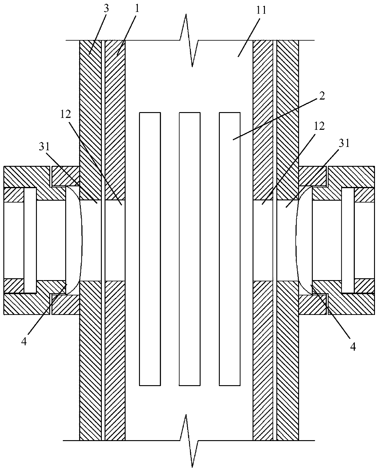
[0058] See attached figure 2 , The difference between this embodiment and Embodiment 1 is that: the number of inner light-transmitting holes 12 is two, and they are symmetrically opened at the midpoint of the axial direction of the two side walls of the inner furnace body 1 . Therefore, the number of light-transmitting components 4 is two groups.
[0059] Other structures of this embodiment are the same as those of Embodiment 1, and will not be repeated here.
PUM
 Abstract
Description
Claims
Application Information